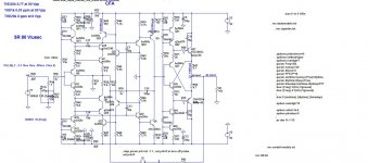
Finally here is non GNFB amp, but with the CFA IPS, where the BJT buffer plays main role, with something lower distortion then pure non GNFB.
This amp could be configured as full GNFB and lower distortion more.
Damir
This amp could be configured as full GNFB and lower distortion more.
Damir
Attachments
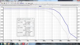
Here is a FFT comparison between the EC power amp with an IPS with no GNFB around it and an IPS with CFA around it. Quite similar harmonics distribution, but IPS CFA with lower distortion. Now which one to choose? I think that both can sound quite similar.
Damir
Damir
Attachments

Hi Damir!
this EC is in general gnfb vfa and probably will react with back emf from the speakers, I am afraid that the sound would be not so excellent like from clear ngnfb amp...
this EC is in general gnfb vfa and probably will react with back emf from the speakers, I am afraid that the sound would be not so excellent like from clear ngnfb amp...
Hi Damir!
this EC is in general gnfb vfa and probably will react with back emf from the speakers, I am afraid that the sound would be not so excellent like from clear ngnfb amp...
Hi Pawel, I don't have practical experience with this EC, so hard to tell.
Damir
information about interface intermodulation distortion
http://www.cordellaudio.com/papers/interface_intermodulation_distortion.pdf
http://www.cordellaudio.com/papers/interface_intermodulation_distortion.pdf
looks good Damir, can you send the .asc files to my mail? would like to test it. Thanks.
Sergio, I am out of my house and PC, only with may tablet, I will send you when I am back.
Damir
No problem Damir 🙂 .
One thing that you have to add is a ground break resistor in the input circuit ground to avoid ground loops in that sensible part of the circuit, normally a 10R.
One thing that you have to add is a ground break resistor in the input circuit ground to avoid ground loops in that sensible part of the circuit, normally a 10R.
No problem Damir 🙂 .
One thing that you have to add is a ground break resistor in the input circuit ground to avoid ground loops in that sensible part of the circuit, normally a 10R.
Thank you Sergio, yes I know that, this is not ready to be built, just simulation, and here the ground break resistor just confuse the thing.
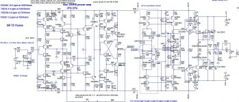
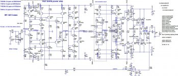
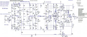
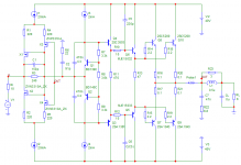
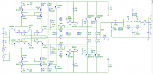
That should be working schematic of the 120 W/8 or 230 W/4
All could be seen from attached pictures.
Damir
All could be seen from attached pictures.
Damir
Attachments
-
 GainWire-ClassB- betterCCS-EC-TT-noGNFB-15V-DCservo-sch.jpg157.2 KB · Views: 1,081
 -
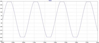
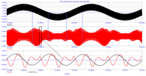
 GainWire-ClassB- betterCCS-EC-TT-noGNFB-15V-DCservo-gain.jpg252.1 KB · Views: 1,042
 -
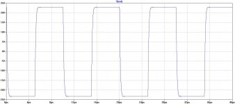 GainWire-ClassB- betterCCS-EC-TT-noGNFB-15V-DCservo-square.jpg82.7 KB · Views: 866
 -
 GainWire-ClassB- betterCCS-EC-TT-noGNFB-15V-DCservo-clipping.jpg94.2 KB · Views: 872
Been waiting a long time here ...... need cfa ips and 200W/8. Fast, ultra low thd.
THx-RNMarsh
Richard, tell me your numbers, what is fast and ultra low THD?
BR Damir
@ RNMarsh
Hi, i'm NOT being funny etc, but i thought that you used to design/build amplifiers commercially. So i'm just wondering why you don't design what you need, & then give us the benefit of your experiences ?
Regards
Hi, i'm NOT being funny etc, but i thought that you used to design/build amplifiers commercially. So i'm just wondering why you don't design what you need, & then give us the benefit of your experiences ?
Regards
@ RNMarsh
Hi, i'm NOT being funny etc, but i thought that you used to design/build amplifiers commercially. So i'm just wondering why you don't design what you need, & then give us the benefit of your experiences ?
Regards
True as in Used to. Now semi-retired at age 72. Lots to tell, dont know where to start. But, Damir's designs are better than anything I did.
THx-RNMarsh
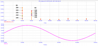
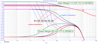
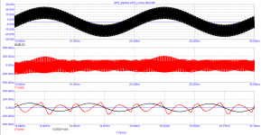
From the point of view of minimizing distortion, the optimal resistance of the resistor R3 is about 240 ohms. At the same time, the output impedance is also minimal, but since the loop gain at a frequency of 20 kHz has a phase shift of more than 60 degrees, the output impedance also has a phase shift. It is known from the distortion spectrum test that when the resistance R3 + -20 Ohm deviates from the nominal value, the level of the 2nd harmonic increases to no more than 0.0035%, and the 3rd harmonic increases to no more than 0.0025%. Measuring the output impedance using an 8 V peak voltage applied across an 8 ohm load to the output of the output stage gives the following results. See Figures. Negative output impedance in some cases can be useful for partial compensation of wire resistance.
ROWEN - schweizer high-end Audio
bible_d 1.pdf
ROWEN - schweizer high-end Audio
bible_d 1.pdf
Attachments
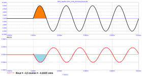
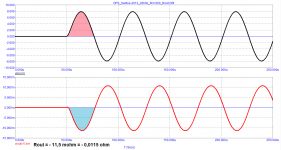
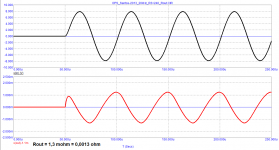
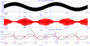
Class AB amplifiers are often subject to switching distortion.Let us measure switching distortion with three values of R3.
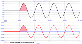
As the test shows with the optimal value of R3, the crossover distortion does not exceed 0.001%, and increases to 0.005% at the extreme values (220 and 260 ohms)
Let's compare the level of crossover distortion with a circuit specially designed to eliminate switching distortion. The circuit is designed according to the principle of Kazuaki Nakayama patent US4595883. The OPS also consists of a Darlington triplet with paired transistors and has a similar quiescent current.
Attachments

- Home
- Amplifiers
- Solid State
- GainWire-NGNFB-classB-PowerAmp