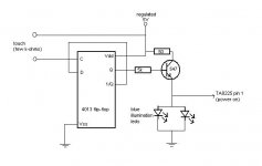
Now while I got this project started, couple questions came to my mind.. Firstly, should the chips be insulated from the heat sink somehow? Toshiba's datasheet doesn't say anything about it. The metal back of the chip seems to be connected to the ground pin. Second, will the circuit below work okay? I thought I could use a simple touch switch in place of a regular one.. the components are just what I happen to have already.
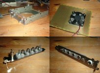
Hope the amp won't run too hot.. The space is somewhat limited
Hope the amp won't run too hot.. The space is somewhat limited
Attachments

If the back side is metal you will probably need insulate it if both devices are on the same heat sink. The exception is if the back connects to the ground pin, and even that may not be the best thing to do. With separare heatsinks, you could forego the insulation so long as the heatsinks were isolated.
But in general, an insulator is a good idea since a "live" heatsink has the potential to cause accidents.
If the back of the device is plastic, it is already isolated so and insulator is not necessary.
But in general, an insulator is a good idea since a "live" heatsink has the potential to cause accidents.
If the back of the device is plastic, it is already isolated so and insulator is not necessary.
I'll answer to myself.. 🙄 Tested the switch circuit today, umm it almost worked. It acted like a capasitive switch when fingertip put near the clock input of the flip-flop. Really it is my first self-designed circuit with transistor in it 😀 Maybe I'll stick to ordinary mechanical switch..
4000 series cmos has input impedance of 10M or more. A few pF of capacitance from you finger will couple plenty of signal (mains hum? static?) into the clock input.
Fix this by adding 100k to 0V and 1nF to 0V, from the clock pin.
I would also add protection diodes from clock to +5 and clock to 0V (reverse biased). Don't underestimate the risk from static discharge (15kV easily - and you wont even feel it)
Fix this by adding 100k to 0V and 1nF to 0V, from the clock pin.
I would also add protection diodes from clock to +5 and clock to 0V (reverse biased). Don't underestimate the risk from static discharge (15kV easily - and you wont even feel it)
Twospoons: thanks, but I'll use that touch switch in some other project in the future.. ordinary switch shall do the job this time! Amp's mechanical parts are beginning to be ready, hope I can start soldering tomorrow. I'm looking forward to get the first tunes out of it at the end of the week.
The connector panel (to the back of the computer) came out to be quite sturdy, I managed to find small enough 4mm banana plug connectors.. the metal plate is from an old isa sound card (or similar).
The connector panel (to the back of the computer) came out to be quite sturdy, I managed to find small enough 4mm banana plug connectors.. the metal plate is from an old isa sound card (or similar).
Attachments
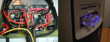
This amp is just never gonna be fully accomplished..  Although it's working fine for now, one problem is quite annoying.. The amp s very sensitive to all kinds of interferences, even when I tested it with 12v car battery (to exclude interference from computer). Slight humming/buzzing sound comes if I put my hand close to the pots (which are metal) and if I knock the power switch, bumping/knocking sound is coming from the speakers. The fan in the heatsink is operating @ 5v and doesn't seem to cause any noise.
Nothing is connected to the computer case, all pots, switches, connectors are insulated. The chips are also insulated from the heatsink. A star "ground" is used. Changing components (if needed) is gonna be quite a nightmare 🙂
more pics here
Although it's working fine for now, one problem is quite annoying.. The amp s very sensitive to all kinds of interferences, even when I tested it with 12v car battery (to exclude interference from computer). Slight humming/buzzing sound comes if I put my hand close to the pots (which are metal) and if I knock the power switch, bumping/knocking sound is coming from the speakers. The fan in the heatsink is operating @ 5v and doesn't seem to cause any noise. Nothing is connected to the computer case, all pots, switches, connectors are insulated. The chips are also insulated from the heatsink. A star "ground" is used. Changing components (if needed) is gonna be quite a nightmare 🙂
more pics here
Attachments
- Status
- Not open for further replies.
- Home
- Amplifiers
- Chip Amps
- gainclone with toshiba TA8225 chips