I trying to create a schematic for the Gain Clone design from Bob Cordell's Audio Power Amplifier Design book. This design improves over the "stock" LM3886 by eliminating the capacitor from the signal path and reducing DC offset. This is my first try at Eagle and wanted someone to look over the schematic. Are the GND & signal ground connections OK ? I keep getting an error about power supply pin connected to V+/V-/GND for the LM3886. Also how do I edit the frame atrributes for author/title etc ?
Thanks
DC
Thanks
DC
Attachments
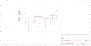
Are the GND & signal ground connections OK ? I keep getting an error about power supply pin
connected to V+/V-/GND for the LM3886.
Is the power ground connected to the analog ground?
Also, it appears that there's no integrator gain for the offset correction.
Last edited:
Power ground is not connected to analog ground. R5 and C1 provide the integrator for offset correction.
Power ground is not connected to analog ground. R5 and C1 provide the integrator for offset correction.
I think the two grounds must be connected for the circuit to function.
Last edited:
.... might be worth a look at Tom Christiansen's "Neurochrome' website - a lot of work done regarding pcb layout and such things
- Status
- Not open for further replies.