There are numerous resources on the internet to build a Gainclone. I have successfully built 4 of them without any dramas, except on one area: Hum and Thump. These can be minimal but in a very quiet night can be very disturbing. My latest build had hum audible at 10cm which is low enough - but not perfect.
Thump is a more serious issue for me. I use the gainclone to drive speakers actively, and without protection to the tweeter. Thump means bye-bye tweeters.
So I researched the issue for about 3 months and it was quite a character building experience . So many times spent trying, untangling wire, ecetera which cost me lots and lots of valuable listening and family time. It has too, cost me a speaker (a test one thankfully).
So now that I finally have a "black amp" so quiet that you could hear your neighbour fart , let's write it down to help beginners and non-engineers like me.
First of all there are excellent resources about grounding. I will list a few which had greatly helped me in this endeavour:
1. Peter Daniel's layout
2. Digi01's post about multi-channel amp grounding
3. Nuuk's (decibel dungeons) grounding
4. RJM Audio binary star grounding
5. LM3875's datasheet, very good ground loop explanation
For each of the contributors above I thank them for their insight about the topic. There is however, a lack of real wiring diagram for a complete, multi-channel, and specially non-PCB Gainclone systems.
So to cut to the chase, here is the final wiring diagram of a 4-channel Gainclone. Have a look and you may get the idea immediately. It is not overly complicated but there are minute criticalities which I will try to explain later.
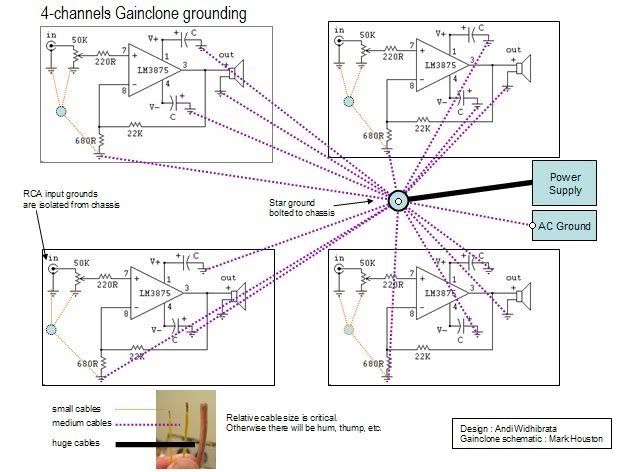
Critical #1
'Separation' of signal ground and output ground. Notice that in the drawing there is a small ground point for inputs per channel, and one big ground point for everyting else. I use the term 'separation' loosely here as they are not really separated in electrical sense. There is a connection between 680R with the input ground, but it is not the same with connecting that input ground to the big centre ground point! This was my first mistake - thinking that connection points are all the same (thinking they measure 0 resistance on the ohm meter anyway)
Critical #2
Run the ground connection separately using cable to each relevant ground point. Yes there is a temptation to 'tidy up' and just use one cable and "hop" to the final ground point - it just won't work. Now, this may be different if you are using PCB as it may have beed designed well with large ground area etched.
Critical #3
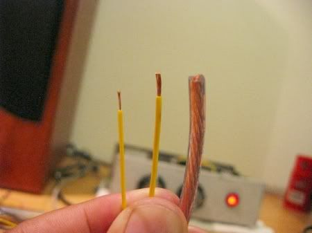
Use different size of wire. Smallest for input ground, medium for output ground, and a really big one for PSU ground. This relates to point 1, and we try to make the signal flow from input ground to PSU ground - not the other way. Electric signal runs like water to the path of least resistance, and we want that path towards the PSU. During my experiment I found that using the same wiring topology, but also same wire throughout caused hum and more annoyingly loud THUMP when the amp is turned off.
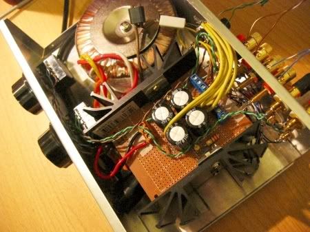
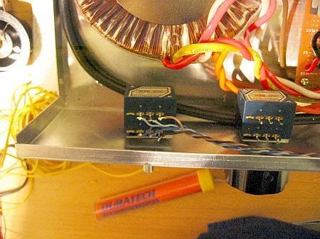
In this photo you can see that my PSU is integrated with the first pair of Gainclone (my second pair would be mounted on top of this). The big cable come from PSU's ground.
Critical #4
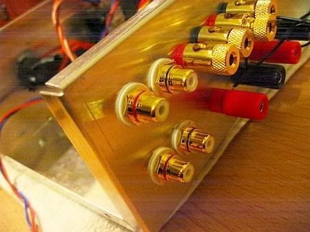
Isolate input RCA ground from the chassis. Enough said, we want to 'control' the flow of signals to each ground point, and chassis is definitely not it. It took me quite sometimes to find RCA terminal with good isolation, found it at Dick Smith for $4 each.
Critical #5
Move the signal cables AWAY from any mains/transformes cables. I noticed that putting the signal wire really close to the amp's switch and cables produced noticeable hum. Good practice is to put potentiometers at the back, as close to the input as possible and use some kind of extention like Peter Daniel's chassis. But as you can see above I don't have the luxury of space by cramming 4 amps into such small chassis. I found out CAT5 cables for signal wiring is both neat and easy to tuck away from the mains/transformer.
Not so critical in terms of hum is that 5ohms resistor to AC ground. Some will question the wisdom of doing this in terms of safety, but it does help. I will leave this to you with disclaimer that yes, it is much safer to directly connect AC ground to the chassis.
There you go, hopefully my experience will help many, and if you're an experienced engineer please let us know if there are any inaccuaracy about the concept of this diagram. Thanks.
Thump is a more serious issue for me. I use the gainclone to drive speakers actively, and without protection to the tweeter. Thump means bye-bye tweeters.
So I researched the issue for about 3 months and it was quite a character building experience
. So many times spent trying, untangling wire, ecetera which cost me lots and lots of valuable listening and family time. It has too, cost me a speaker (a test one thankfully).So now that I finally have a "black amp" so quiet that you could hear your neighbour fart
, let's write it down to help beginners and non-engineers like me.First of all there are excellent resources about grounding. I will list a few which had greatly helped me in this endeavour:
1. Peter Daniel's layout
2. Digi01's post about multi-channel amp grounding
3. Nuuk's (decibel dungeons) grounding
4. RJM Audio binary star grounding
5. LM3875's datasheet, very good ground loop explanation
For each of the contributors above I thank them for their insight about the topic. There is however, a lack of real wiring diagram for a complete, multi-channel, and specially non-PCB Gainclone systems.
So to cut to the chase, here is the final wiring diagram of a 4-channel Gainclone. Have a look and you may get the idea immediately. It is not overly complicated but there are minute criticalities which I will try to explain later.
Critical #1
'Separation' of signal ground and output ground. Notice that in the drawing there is a small ground point for inputs per channel, and one big ground point for everyting else. I use the term 'separation' loosely here as they are not really separated in electrical sense. There is a connection between 680R with the input ground, but it is not the same with connecting that input ground to the big centre ground point! This was my first mistake - thinking that connection points are all the same (thinking they measure 0 resistance on the ohm meter anyway)
Critical #2
Run the ground connection separately using cable to each relevant ground point. Yes there is a temptation to 'tidy up' and just use one cable and "hop" to the final ground point - it just won't work. Now, this may be different if you are using PCB as it may have beed designed well with large ground area etched.
Critical #3
Use different size of wire. Smallest for input ground, medium for output ground, and a really big one for PSU ground. This relates to point 1, and we try to make the signal flow from input ground to PSU ground - not the other way. Electric signal runs like water to the path of least resistance, and we want that path towards the PSU. During my experiment I found that using the same wiring topology, but also same wire throughout caused hum and more annoyingly loud THUMP when the amp is turned off.
In this photo you can see that my PSU is integrated with the first pair of Gainclone (my second pair would be mounted on top of this). The big cable come from PSU's ground.
Critical #4
Isolate input RCA ground from the chassis. Enough said, we want to 'control' the flow of signals to each ground point, and chassis is definitely not it. It took me quite sometimes to find RCA terminal with good isolation, found it at Dick Smith for $4 each.
Critical #5
Move the signal cables AWAY from any mains/transformes cables. I noticed that putting the signal wire really close to the amp's switch and cables produced noticeable hum. Good practice is to put potentiometers at the back, as close to the input as possible and use some kind of extention like Peter Daniel's chassis. But as you can see above I don't have the luxury of space by cramming 4 amps into such small chassis. I found out CAT5 cables for signal wiring is both neat and easy to tuck away from the mains/transformer.
Not so critical in terms of hum is that 5ohms resistor to AC ground. Some will question the wisdom of doing this in terms of safety, but it does help. I will leave this to you with disclaimer that yes, it is much safer to directly connect AC ground to the chassis.
There you go, hopefully my experience will help many, and if you're an experienced engineer please let us know if there are any inaccuaracy about the concept of this diagram. Thanks.
With a proper PCB everything is smuch easier.
I assume you do not suggest to run all those individual ground wires if they are connected on a common ground plane of the PCB. Connecting input grounds to the star yes, but all of them,hmmm.
I assume you do not suggest to run all those individual ground wires if they are connected on a common ground plane of the PCB. Connecting input grounds to the star yes, but all of them,hmmm.
Yes. If you use PCB then the grounding would be designed properly then. Like in Peter Daniel's instruction.
Actually there is an easier way:each channel has it's own star ground,then connect those 4 star grounds together at one point.
Actually there is an easier way:each channel has it's own star ground,then connect those 4 star grounds together at one point.
I'm sure I did that early in my experiment, but still got hum.
Leolabs said:Actually there is an easier way:each channel has it's own star ground,then connect those 4 star grounds together at one point.
Sorry. But that would not be optimal.
It would partially defeat the purpose of the star grounding scheme: You'd still have the large and dynamic ground-return currents sharing the same conductor, with each other as well as with the signal input's ground reference point.
The ground-return conductor that they share has impedance, i.e. resistance and inductance, at least. The various return currents all induce voltages across that impedance, according to both V = IR and V=L(di/dt), where R and L are part of the shared conductor's impedance, i is current magnitude, and di/dt is rate-of-change of current magnitude. [The induced voltages can very easily be 10's of mV (or even 100's of mV), peak-to-peak.]
The induced voltages all add together and appear back at the non-ground end of the ground-return conductor, and everywhere it connects.
That means that the signal input ground reference point would then not be 'zero volts'. It would be varying according to the voltages induced across the shared ground-return conductor.
The amplifier only sees, as its input signal, the voltage-difference between the signal input point and the signal input ground reference point. So all of those nasty voltage variations would be directly arithmetically summed with the input signal. Not good.
Thank You!
Gainphile: Thank you for taking the time to share your hard-earned knowledge so throughly. The graphics and pictures are great too!
I dealt (somewhat successfully) with a HUGE turn-on thump issue with my first amp build a few months ago. It almost soured my from building anything else. I can see where this would have saved me a lot of hours. And now I see things I should consider doing next time I have the case open to chase down the last few hum gremlins.
Thanks again!
🙂
DECKY999 said:With a proper PCB everything is smuch easier.
I assume you do not suggest to run all those individual ground wires if they are connected on a common ground plane of the PCB. Connecting input grounds to the star yes, but all of them,hmmm.
If the power supply is on the same PCB, then with a ground plane you wouldn't need separate conductors, except maybe still for the input ground reference.
If the power supply is on a different PCB, a ground plane on the amplifier PCB doesn't do as much good. It might be OK, as long as you use a separate wire for the input ground return (since any induced ground bounce voltage, there, gets directly amplified by the gain of the amp). But why not also split up the grounding for the speaker return and the power/decoupling return? The speaker return, especially, can have very large and dynamic currents. Why let it modulate your power rails? It's only one more wire, after all. And the speaker return-current doesn't need to go back to the PCB, anyway.
Hi gainphile,
Thanks for posting your diagram! That's a great idea.
I am not completely certain, at the moment, but, I think it might be better to have the power pins' decoupling grounds connected at the chipamp, which would mean that they'd have to (or might as well, at least) share a single ground-return conductor.
Did you try it with them connected at the chip, and still get hum?
If the power pins' decoupling grounds are NOT connected at the chipamp, then it would probably be a good idea to add a small capacitor, 0.1uF or 0.22 uF, directly between the two power supply pins of the chip.
Hi gainphile,
AndrewT will probably soon comment on your 5-Watt 5-Ohm 'safety disconnect' network. 🙂 By the way, he recently started a very good thread about 'safety disconnect' networks, with some actual high-current fault-test results, IIRC.
I think that many people also connect a very-high-current bridge rectifier in parallel with the resistor, and also put a small-value (0.1 uF) capacitor in parallel with the resistor. And, very often, the resistor's value is somewhere from 10 Ohms to 100 Ohms.
As I'm sure you know (besides lifting the system ground slightly above any disturbances in the earth ground, I guess it is), the main idea is to be able to pass a worst-case fault current, for a long-enough time to allow a mains circuit breaker to trip. [That's also why the safety disconnect network should not have solder used to attach it. It must be bolted or welded, since a large fault current could possibly melt solder, undoing the safety connection to earth ground.]
The concern is, I think, that the component(s) in the disconnect network might fail before the mains circuit breaker trips, allowing a lethal fault condition to remain, powered by the mains.
Your 5-Watt resistor's datasheet should indicate how long it can survive various overload conditions. Assuming that the 5-Ohm resistor had 115VAC applied across it, the current through it would be 23 Amps RMS, giving a power dissipation of 2645 Watts.
That sounds like a lot. But I regularly dissipate almost 1000 Watts in a similar 5W resistor, for up to tens of milliseconds or so at a time (but at widely-separated times, such as no more than once every few minutes), and the resistor never even gets detectably warmer to the touch.
At any rate, a couple of huge anti-parallel diodes (or series pairs in anti-parallel, for more separation voltage from earth ground disturbances), or a large bridge rectifier, if placed in parallel with your 5W resistor, would help to make your system safer. (And there must be some good reason why most people also use a parallel 0.1uF capacitor.)
Sorry to have blathered-on, for so long, about all of that.
-----
P.S. How is your power supply configured? I have seen questions from people wondering how to avoid hum when using a single supply to power multiple chipamps. If you could make a schematic, or better yet maybe, a layout and wiring diagram, and show exactly how you did the grounding, that might be extremely helpful for a lot of people.
You're most welcome !
This is nothing new as I got the information from those links at the start of the article. Just emphasizing few critical points.
Of course there are more elegant and simpler way like using good PCB but I think the concept is the same.
This is nothing new as I got the information from those links at the start of the article. Just emphasizing few critical points.
Of course there are more elegant and simpler way like using good PCB but I think the concept is the same.
Hi Gain,
I think Tom has explained the Safety implications well enough for you to take action AND modify the diagrams in post1.
I think Tom has explained the Safety implications well enough for you to take action AND modify the diagrams in post1.
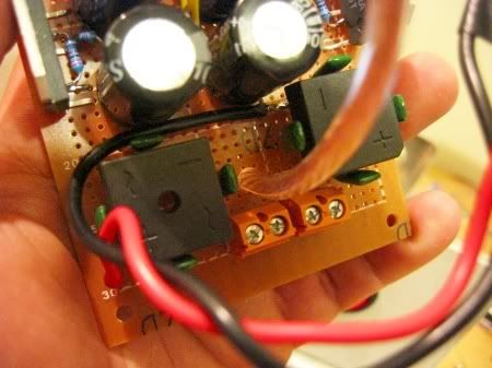
Hi Gainphile! I'm so curious. What are the 8 little green Tracon 100v Polyester caps, and what do they do to the bridge rectifiers? It looks cool. . .
Thanks, very helpful post. I'm about to assemble a couple of chip amps and was wondering about grounding. You've solved my problem
Hi Gainphile! I'm so curious. What are the 8 little green Tracon 100v Polyester caps, and what do they do to the bridge rectifiers? It looks cool. . .
They are snubber capacitors. Supposedly to surpress HF ripple but I really don't know what they do. I just followed the diagram from:
http://diyaudioprojects.com/Chip/Synergy-LM3875-Gainclone/index.htm
Thanks Gainphile and everyone else for the excellent posts.
I've got a couple of newbie questions.
I realize that the exact wire gauges may not be critical, but could you give me an idea of the relative sizes of the small, medium and huge ground wires?
Also, I'm currently finishing up a BrianGT 3875 dual mono chipamp kit (it's been lying around here for a LONG time), and was wondering if it would reduce the hum and thump potential more if it's built with single or dual power supply boards.
GooTees' 'antiparallel' diodes had me a bit confused, so I Google'd 'audio safety ground disconnect' and came across a page on the ESP site with a wiring diagram. I assume that this is what you meant when you talked about adding a bridge rectifier and capacitor?
http://sound.westhost.com/earthing.htm
Again, thanks everyone. This post has got me interested in putting together a hand-wired, thumpless 'black' amp next. That way, the next time my wife asks me what we're going to do with all of my speakers, I can tell her not to worry, I'm building amplifiers to power them 😀
Mike514ml
Mike514ml said:Thanks Gainphile and everyone else for the excellent posts.
I've got a couple of newbie questions.
I realize that the exact wire gauges may not be critical, but could you give me an idea of the relative sizes of the small, medium and huge ground wires?
Also, I'm currently finishing up a BrianGT 3875 dual mono chipamp kit (it's been lying around here for a LONG time), and was wondering if it would reduce the hum and thump potential more if it's built with single or dual power supply boards.
GooTees' 'antiparallel' diodes had me a bit confused, so I Google'd 'audio safety ground disconnect' and came across a page on the ESP site with a wiring diagram. I assume that this is what you meant when you talked about adding a bridge rectifier and capacitor?
http://sound.westhost.com/earthing.htm
Again, thanks everyone. This post has got me interested in putting together a hand-wired, thumpless 'black' amp next. That way, the next time my wife asks me what we're going to do with all of my speakers, I can tell her not to worry, I'm building amplifiers to power them 😀
Mike514ml
Yes. Figure 3, IIRC.
gainphile said:
They are snubber capacitors. Supposedly to surpress HF ripple but I really don't know what they do. I just followed the diagram from:
http://diyaudioprojects.com/Chip/Synergy-LM3875-Gainclone/index.htm
Those small bypass caps on the rectifier bridge reduce the diode switching noises and results in cleaner DC.
I see that the Safety Earth connection is still shown wrongly in post1.
When are you planning to ask the Mods to substitute a safe diagram?
When are you planning to ask the Mods to substitute a safe diagram?
- Status
- Not open for further replies.
- Home
- Amplifiers
- Chip Amps
- Gainclone HUM, THUMP problems - The solution