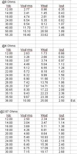
Hello, i decided to build a Gainclone amp for a pair of Markaudio CHN-50 since it can drive 4 ohms at 7 watts according to this table that i got from another post (attached below). As far as i have learn the power output depends on the power supply voltage and for 7 watts should be around 20-21 volts but i don't know how to calculate the power supply transformer specs, so i need to know:
1.- Is there a formula or procedure to calculate the power supply current or should i simulate the schematic?
2.- The transformer should be able to deliver more current than needed for safety? if so by how much?
3.- How to estimate the dimensions of the heat sink?
I hope you can help me out, have a nice one, cheers.
Attachments
You don't want to build a 7 watt amplifier. A little headroom doesn't hurt. There is always the next speaker project. Look for a 50 volt center tap transformer ie 25-0-25 volts A.C.. that will give you around +/- 35 volts DC give or take line voltage up or down, diode losses etc. That should give you around 50watts or so. Good luck on your project.

I generally recommend ±28 to ±30 V for a gainclone. That gives you about 40 W into 8 Ω and 65 W into 4 Ω. If you want to run at lower power, all you have to do is to drop the supply voltage. ±24 V is a good spot as there are many SMPSes available that can deliver +24 V and two of those in series gives you ±24 V. That'll give you 28 W into 8 Ω and around 50 W into 4 Ω. The Mean Well RPS-200-24 would be a good one.
You can go even lower if you want (±10 V is the lowest) but there's little point in that. It's nice to have a little extra margin (or headroom).
You can certainly calculate the supply current. It's going to be the load current plus the quiescent current of the LM3886. The quiescent current is much lower than the load current, so approximating the supply current as equal to the load current would make sense.
Transformers are typically spec'ed to 140-160% over the VA product of the load voltage/current for a DC load. That's to account for the rather gnarly current waveform through the rectifier.
Tom
The chart you posted is for LM1875, somewhat applicable to TDA2050, LM1876, etc.
While Gainclone usually means LM3876 or LM3886 based chip amp which has bit higher PSU requirements
1 Yes there are https://www.circuitbasics.com/tda2050-diy-amplifier-build-guide/#PCB-Design-Tips
If I had to do, for LM1875 pair, I would go for 12-0-12 / 5A Transformer with 5A or above rectifier diodes and 4700uF X 4 filter caps.
For SMPS +/-12 (for 4Ohms) to +/- 18V (for 8Ohms) with 220uF to 1000uF caps near LM1875. SMPS dont like 10,000uF hanging on its output
Advantages of using lower supply voltages are -
ability to drive lower impedance speakers as chipamps are current starved
lower heat dissipation, so lower thermal induced distortion
longer component life
2 For LM1875 pair in above example, going for 8-10A tranny is more than enough
3 I usually reuse old CPU heatsinks, weighing more 250gms, just a rule of thumb
https://www.circuitbasics.com/design-hi-fi-audio-amplifier-lm3886/
Currently everything is in short supply, try TDA7294
While Gainclone usually means LM3876 or LM3886 based chip amp which has bit higher PSU requirements
1 Yes there are https://www.circuitbasics.com/tda2050-diy-amplifier-build-guide/#PCB-Design-Tips
If I had to do, for LM1875 pair, I would go for 12-0-12 / 5A Transformer with 5A or above rectifier diodes and 4700uF X 4 filter caps.
Advantages of using lower supply voltages are -
ability to drive lower impedance speakers as chipamps are current starved
lower heat dissipation, so lower thermal induced distortion
longer component life
2 For LM1875 pair in above example, going for 8-10A tranny is more than enough
3 I usually reuse old CPU heatsinks, weighing more 250gms, just a rule of thumb
https://www.circuitbasics.com/design-hi-fi-audio-amplifier-lm3886/
Currently everything is in short supply, try TDA7294
Last edited:
Thanks for your reply, im kinda stuck on those 7 watts because me and a group of non technical people are going to build 5 stereo systems for desktop monitors and i can't be sure they will know how to power them properly, if it was only me i would know how much power can i put on those speaker but for the others i need to fool proof them, cheersYou don't want to build a 7 watt amplifier. A little headroom doesn't hurt. There is always the next speaker project. Look for a 50 volt center tap transformer ie 25-0-25 volts A.C.. that will give you around +/- 35 volts DC give or take line voltage up or down, diode losses etc. That should give you around 50watts or so. Good luck on your project.
Thanks for that info Tom, so 7 watts in 4 ohms should be about 5.29 volts using W= (VxV)/R (i dont know how to write V square xd) and I will be 1,32A using I=V/R and that should be doubled for 2 channels plus the quiescent current in the datasheet should be the total Current... so i guess i need a transformer with at least 3 Amps on the secondary, thanks for your help man!!! CheersI generally recommend ±28 to ±30 V for a gainclone. That gives you about 40 W into 8 Ω and 65 W into 4 Ω. If you want to run at lower power, all you have to do is to drop the supply voltage. ±24 V is a good spot as there are many SMPSes available that can deliver +24 V and two of those in series gives you ±24 V. That'll give you 28 W into 8 Ω and around 50 W into 4 Ω. The Mean Well RPS-200-24 would be a good one.
You can go even lower if you want (±10 V is the lowest) but there's little point in that. It's nice to have a little extra margin (or headroom).
You can certainly calculate the supply current. It's going to be the load current plus the quiescent current of the LM3886. The quiescent current is much lower than the load current, so approximating the supply current as equal to the load current would make sense.
Transformers are typically spec'ed to 140-160% over the VA product of the load voltage/current for a DC load. That's to account for the rather gnarly current waveform through the rectifier.
Tom
You'll want to over-size by 140-160%, so that gets you to 1.32*2*1.4 = 3.7 A, minimum. That does assume that the amp will be running flat-out with a sine wave, though. Most of use listen to music, so you can scale it back by quite a bit. If you design for 1 W per channel on average you're probably good. I'd probably get a 50 VA transformer and even that would be overkill for a 2x7 W amp.
Tom
Tom
Thanks, lots of good info on your reply!!! ... i didn't even thought about SMPS until you said it. Now that i think about it maybe TDA2050 its a better option since it uses a simple power supply instead of a bipolar one and maybe with some luck a notebook power supply can do the trick if regulated and using enough filtering.The chart you posted is for LM1875, somewhat applicable to TDA2050, LM1876, etc.
While Gainclone usually means LM3876 or LM3886 based chip amp which has bit higher PSU requirements
1 Yes there are https://www.circuitbasics.com/tda2050-diy-amplifier-build-guide/#PCB-Design-Tips
If I had to do, for LM1875 pair, I would go for 12-0-12 / 5A Transformer with 5A or above rectifier diodes and 4700uF X 4 filter caps.
For SMPS +/-12 (for 4Ohms) to +/- 18V (for 8Ohms) with 220uF to 1000uF caps near LM1875. SMPS dont like 10,000uF hanging on its output
Advantages of using lower supply voltages are -
ability to drive lower impedance speakers as chipamps are current starved
lower heat dissipation, so lower thermal induced distortion
longer component life
2 For LM1875 pair in above example, going for 8-10A tranny is more than enough
3 I usually reuse old CPU heatsinks, weighing more 250gms, just a rule of thumb
https://www.circuitbasics.com/design-hi-fi-audio-amplifier-lm3886/
Currently everything is in short supply, try TDA7294
What do you think of using something like this, is the lack of a earth connection something to be worried about?
http://www.onebattery.co.uk/imgbig/GSB005.jpg
LM1875 and other ICs can also be used in a single supply mode, but amps based on bipolar supply sounds best
You will get tingling sensation, whenever you come in contact with any metalic parts like input pin , bare speaker wire, etc
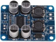
If all of your group members are noobs, I suggest you go for PBTL3118 class D module pair as a first project. Cheap but good sound, minimal soldering and simple connections. Only drawback is, barely noticeable high frequency noise from sensitive tweeters during silent passages. I'm using it currently as a PC audio amp. Give it a try, you will like it
You will get tingling sensation, whenever you come in contact with any metalic parts like input pin , bare speaker wire, etc
If all of your group members are noobs, I suggest you go for PBTL3118 class D module pair as a first project. Cheap but good sound, minimal soldering and simple connections. Only drawback is, barely noticeable high frequency noise from sensitive tweeters during silent passages. I'm using it currently as a PC audio amp. Give it a try, you will like it
Attachments
Thanks for your suggestion, i was trying to get away from Class D, im going to check if someone has reviewed that IC, maybe i change my mind, cheersLM1875 and other ICs can also be used in a single supply mode, but amps based on bipolar supply sounds best
You will get tingling sensation, whenever you come in contact with any metalic parts like input pin , bare speaker wire, etc
If all of your group members are noobs, I suggest you go for PBTL3118 class D module pair as a first project. Cheap but good sound, minimal soldering and simple connections. Only drawback is, barely noticeable high frequency noise from sensitive tweeters during silent passages. I'm using it currently as a PC audio amp. Give it a try, you will like it
- Home
- Amplifiers
- Chip Amps
- Gainclone for 4ohms@7 watts, power supply questions