How can i measure the current that my gainclone draws? when i connect my multimeter in series with the power rails, the amp only outputs distortion.
This will only work with your multimeter at DC and at high range - several amps. Otherwise, it will have too much resistance.
You can olso place a smallish resistor in series with the supply (<1Ohm I would say) and measure the voltage drop, then I=V/R.
Jan Didden
You can olso place a smallish resistor in series with the supply (<1Ohm I would say) and measure the voltage drop, then I=V/R.
Jan Didden
A few questions for you. If you answer these yes (correctly) you should be measuring the current supplied by the power supply to the gain clone.
1) Is the meter on the highest current scale?
Most VOMs or DVM have a 10 amp range and you should start out on that range. The lower ranges will have a higher internal resistance of the meter and may be fuse protected. If the fuse blowes then one side of the power supply will not be supplied to the amp and the sound will be very distorted.
2) Is the + meter lead connected to the power supply + and the - meter lead connected to the amp. + power connection?
Make sure to do this correctly and remember that high current could be present at this point so very good connections are a must.
3) Can the leads on your meter handle the current or are they to light?
Most meter leads that come with VOMs or DVMs use a small gauge wire (20 - 24 gage). For high curent loads this can cause problems. I would suggest making a special set of cables for current measurments that can easly pass high levels of current safely.
Check these points and let us know how you make out.
later BZ
PS this all assumes the amp sounded good before you tried to measure he current.
1) Is the meter on the highest current scale?
Most VOMs or DVM have a 10 amp range and you should start out on that range. The lower ranges will have a higher internal resistance of the meter and may be fuse protected. If the fuse blowes then one side of the power supply will not be supplied to the amp and the sound will be very distorted.
2) Is the + meter lead connected to the power supply + and the - meter lead connected to the amp. + power connection?
Make sure to do this correctly and remember that high current could be present at this point so very good connections are a must.
3) Can the leads on your meter handle the current or are they to light?
Most meter leads that come with VOMs or DVMs use a small gauge wire (20 - 24 gage). For high curent loads this can cause problems. I would suggest making a special set of cables for current measurments that can easly pass high levels of current safely.
Check these points and let us know how you make out.
later BZ

PS this all assumes the amp sounded good before you tried to measure he current.
janneman said:This will only work with your multimeter at DC and at high range - several amps. Otherwise, it will have too much resistance.
You can olso place a smallish resistor in series with the supply (<1Ohm I would say) and measure the voltage drop, then I=V/R.
Jan Didden
i will try the resistor method.
HDTVman said:A few questions for you. If you answer these yes (correctly) you should be measuring the current supplied by the power supply to the gain clone.
1) Is the meter on the highest current scale?
Most VOMs or DVM have a 10 amp range and you should start out on that range. The lower ranges will have a higher internal resistance of the meter and may be fuse protected. If the fuse blowes then one side of the power supply will not be supplied to the amp and the sound will be very distorted.
2) Is the + meter lead connected to the power supply + and the - meter lead connected to the amp. + power connection?
Make sure to do this correctly and remember that high current could be present at this point so very good connections are a must.
3) Can the leads on your meter handle the current or are they to light?
Most meter leads that come with VOMs or DVMs use a small gauge wire (20 - 24 gage). For high curent loads this can cause problems. I would suggest making a special set of cables for current measurments that can easly pass high levels of current safely.
Check these points and let us know how you make out.
later BZ
PS this all assumes the amp sounded good before you tried to measure he current.
my multimeter automatically sets the current scale, ill try turning this feature off and trying again with the highest setting.
I suggest using a shunt resistor
I personally use a hall effect transformer for my meter and I use a clamp on meter for mains voltage
DIRT®
I personally use a hall effect transformer for my meter and I use a clamp on meter for mains voltage
DIRT®
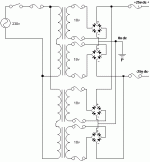
I am building a power suply using this diagram. How can i work out what value of fuse i need on the primary side of the transformer. Is it sensible to measure the current using my multimeter, or should i just multiply the current at the secondary by the ratio of the transformer? The current at the secondary is 15A max, so i will use a 15A slowblow here, then a 15A quickblow after the capacitors, so the inrush current doesnt blow the first fuse.
230v/36v=6.4
15A/6.4=2.4A
Should i use a 3A slowblow, or will the transformers (2x 300VA) blow it? should i build a soft start circuit, with a lower value (2A maybe)?
230v/36v=6.4
15A/6.4=2.4A
Should i use a 3A slowblow, or will the transformers (2x 300VA) blow it? should i build a soft start circuit, with a lower value (2A maybe)?
Attachments
Konnichiwa,
May I polietley ask WHY ON EARTH you would do that? You have separate transformers and rectifiers so you can supply both channels fully separated with the grounds only connecting at each channels star earth point, thus making sure all current loops and grounds are optimised and you simply throw away all these advantages. I would really recommend for you to change this.
There should be a fuse PER TRANSFORMER and the value for this fuse and the type is usually specified by the transformer manufacturer as mandatory application to retain the transformers safety certification.
Absolutely NO.
Better choice, but you really should get that manufacturers recommendation for this.
Sayonara
Matttcattt said:I am building a power suply using this diagram.
May I polietley ask WHY ON EARTH you would do that? You have separate transformers and rectifiers so you can supply both channels fully separated with the grounds only connecting at each channels star earth point, thus making sure all current loops and grounds are optimised and you simply throw away all these advantages. I would really recommend for you to change this.
Matttcattt said:How can i work out what value of fuse i need on the primary side of the transformer.
There should be a fuse PER TRANSFORMER and the value for this fuse and the type is usually specified by the transformer manufacturer as mandatory application to retain the transformers safety certification.
Matttcattt said:Is it sensible to measure the current using my multimeter,
Absolutely NO.
Matttcattt said:or should i just multiply the current at the secondary by the ratio of the transformer?
Better choice, but you really should get that manufacturers recommendation for this.
Sayonara
Kuei Yang Wang said:
May I polietley ask WHY ON EARTH you would do that?
It seems like he's trying to save on fuses after the bridges, I don't see any other explanation😉
This PS circuit needs only two fuses (on primaries), using more is asking for trouble.
yes i want to protect my amps.
my amp has 16 channels, which are already wired together. the amp is finished, and has only one input for power (a four pin connector: +v, 0v, 0v, -v).
so the transformers should have information about the fuse rating to use?
my amp has 16 channels, which are already wired together. the amp is finished, and has only one input for power (a four pin connector: +v, 0v, 0v, -v).
so the transformers should have information about the fuse rating to use?
Matttcattt, I think you should ask yourself: WHAT do I use the fuses for? It's no harm to use so many fuses but for what?
First of all, you need primary fuses to avoid damage of the transformer but the rest? I let you answer this first.
First of all, you need primary fuses to avoid damage of the transformer but the rest? I let you answer this first.
IME a fuse generally screws the sound up big time. It annoys me enough there are fuses outside my flat i can do nothing about...
Eleven of them? Dunno, maybe the distortions cancel each other out 🙂 What exactly are trying to protect? The transformers? The chips? They cost almost as little as the fuses and are seriously protected as is. You're certainly not doing the speakers many favours with the fuses in the secondaries - one open fuse may result dc at output.
Eleven of them? Dunno, maybe the distortions cancel each other out 🙂 What exactly are trying to protect? The transformers? The chips? They cost almost as little as the fuses and are seriously protected as is. You're certainly not doing the speakers many favours with the fuses in the secondaries - one open fuse may result dc at output.
Kuei Yang Wang said:Konnichiwa,
May I polietley ask WHY ON EARTH you would do that? You have separate transformers and rectifiers so you can supply both channels fully separated with the grounds only connecting at each channels star earth point, thus making sure all current loops and grounds are optimised and you simply throw away all these advantages. I would really recommend for you to change this.
[snip]Sayonara
Fully agree. Connecting those bridges together will cause one transformer to do much more work charging the caps than the other, because they will never be exactly the same. Folloy KYW's advice, make two supplies, one for +V and one for -V. You will also save big time on the bridges (in fact you would need only 4 diodes in total).
Jan Didden
peranders said:Matttcattt, I think you should ask yourself: WHAT do I use the fuses for? It's no harm to use so many fuses but for what?
First of all, you need primary fuses to avoid damage of the transformer but the rest? I let you answer this first.
the secondaries are to protect the bridges, and the last ones are to protect my amp, or any other load attacted.
if there are serious disadvantage (other than audiophiles thinking the fuses affect the sound), i might think about using less fuses.
janneman said:
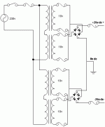
Fully agree. Connecting those bridges together will cause one transformer to do much more work charging the caps than the other, because they will never be exactly the same. Folloy KYW's advice, make two supplies, one for +V and one for -V. You will also save big time on the bridges (in fact you would need only 4 diodes in total).
Jan Didden
like this?
Attachments
You don't need "double" fuses for the rectifier bridges. The primary fuses are enough if your bridges are big enough. A 10 A bridge can take 100 A shortly. A 25 A can take ...much before it goes to powder.Matttcattt said:
the secondaries are to protect the bridges, and the last ones are to protect my amp, or any other load attacted.
peranders said:
You don't need "double" fuses for the rectifier bridges. The primary fuses are enough if your bridges are big enough. A 10 A bridge can take 100 A shortly. A 25 A can take ...much before it goes to powder.
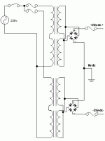
i am going to use 35A bridges, so i dont need the fuses?
[EDIT]: back to my original question, what value of fuse should i use for the primaries?
Attachments
Your original question: How much current goes at full load? If you not are going to use any soft start, 5 or 6.3 AT for 600 VA With softstart 3.15-5 AT, it depends. You should in any case use a slow fuse.
Some transformer manufactures use to have recommendations on the transformer. Check the label.
Some transformer manufactures use to have recommendations on the transformer. Check the label.
Konnichiwa,
How about something like this:
http://ampchipdiy.com/ultimate_ps_gc_1.gif
Only scale up the two 4,700uF Capacitors to maybe 22,000uF/16V or therabouts.
Sayonara
Matttcattt said:like this?
How about something like this:
http://ampchipdiy.com/ultimate_ps_gc_1.gif
An externally hosted image should be here but it was not working when we last tested it.
Only scale up the two 4,700uF Capacitors to maybe 22,000uF/16V or therabouts.
Sayonara
peranders said:Your original question: How much current goes at full load? If you not are going to use any soft start, 5 or 6.3 AT for 600 VA With softstart 3.15-5 AT, it depends. You should in any case use a slow fuse.
Some transformer manufactures use to have recommendations on the transformer. Check the label.
would you advise a soft-start circuit? like this one?: http://www.sound.westhost.com/project39.htm
thanks for the help.
Kuei Yang Wang said:Konnichiwa,
How about something like this:
http://ampchipdiy.com/ultimate_ps_gc_1.gifAn externally hosted image should be here but it was not working when we last tested it.
Only scale up the two 4,700uF Capacitors to maybe 22,000uF/16V or therabouts.
Sayonara
what advantages would this give?
- Status
- Not open for further replies.
- Home
- Amplifiers
- Chip Amps
- Gainclone Current


