A very similar circuit was used by Rupert Neve in one of his early all tube mixers in the early 60s (the schematic is somewhere on the net). The main difference is he feeds g2 via a resistor and decouples it so there is only NFB at dc.
Cheers
Ian
Cheers
Ian
Another variation for your consideration - I've seen a 6BL8 (ECF80) triode/pentode used in a well regarded pre/line amp.
The pentode section was used as the cathode follower. g1 + g2 drive to the CF with the g2 drive via the triode section also wired as a cathode follower. g1 and g2 drive same phase with g2 drive AC voltage approx 30% of g1 drive. Now my first impression of that is that is a bit "weird" - would'nt that represent positive feedback to the screen?
Cheers,
Ian (also)
A very similar circuit was used by Rupert Neve in one of his early all tube mixers
Look at the diagram in post #14 of this thread. It sounds like the same thing....it came from an old RCA tube manual.
http://www.diyaudio.com/forums/tube...simplep-p.html?highlight=magic+phase+splitter
Look at the diagram in post #14 of this thread. It sounds like the same thing....it came from an old RCA tube manual.
http://www.diyaudio.com/forums/tube...simplep-p.html?highlight=magic+phase+splitter
Ruprt Neve's circuit is virtually identical apart from the triode is a CF. Maybe the RCA tube manual was his inspiration.
Cheers
Ian
Attachments
Ruprt Neve's circuit is virtually identical apart from the triode is a CF. Maybe the RCA tube manual was his inspiration.
Possibly, although this is a very well-known and obvious topology, so he may well have thought of it independently (most people who use pentodes probably have). A cascode version of this circuit was patented a few years ago too: US4647872 (rather pointlessly as it happens, because that too was an old and obvious circuit!).
Last edited:
Another variation for your consideration - I've seen a 6BL8 (ECF80) triode/pentode used in a well regarded pre/line amp.
The pentode section was used as the cathode follower. g1 + g2 drive to the CF with the g2 drive via the triode section also wired as a cathode follower. g1 and g2 drive same phase with g2 drive AC voltage approx 30% of g1 drive. Now my first impression of that is that is a bit "weird" - would'nt that represent positive feedback to the screen?
Sounds like a bootstrapped circuit which aims to reduce the input capacitance of the cathode follower by feeding the output signal back to the screen grid, so there is less (signal) voltage difference between G1 and G2. It sounds similar to the cascoded version popular with Allen Wright; http://www.vacuumstate.com/images_upload/gross/fvp5_rev_1_s.gif
see also "An AC cathode-follower circuit of very high input impedance", J.R.Macdonald, Review of Scientific Instruments, Feb 1954.
Wow who'd have thought I'd end up at Neve...!Rupert Neve's circuit is virtually identical apart from the triode is a CF. Maybe the RCA tube manual was his inspiration.
Ian
Ian, which circuit was that from? I've never actually seen the valve equipment schematics 🙄
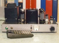
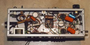
That is a new 'old' cct. When I still had hair I used it in two PPUL 6L6GCs circa 1960. Still have them here on the shelf, still working. Some caps had to be replaced over many years. The OPTs are noname from Japan but quality, they came with freq response traces on graph paper.😀
And also appears in the last RCA Receiving Tube Manual RC30, p695.🙂
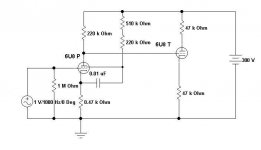
The cct is a form of DC NFB & helps stabilize the tube pair. But the cct it replaces is just as effective, the pentode G2 resistor provides a large DC NFB that stabilizes the OP same as the cathode resistor.
And also appears in the last RCA Receiving Tube Manual RC30, p695.🙂
The cct is a form of DC NFB & helps stabilize the tube pair. But the cct it replaces is just as effective, the pentode G2 resistor provides a large DC NFB that stabilizes the OP same as the cathode resistor.
Attachments
Wow who'd have thought I'd end up at Neve...!
Ian, which circuit was that from? I've never actually seen the valve equipment schematics 🙄
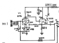
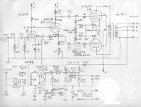
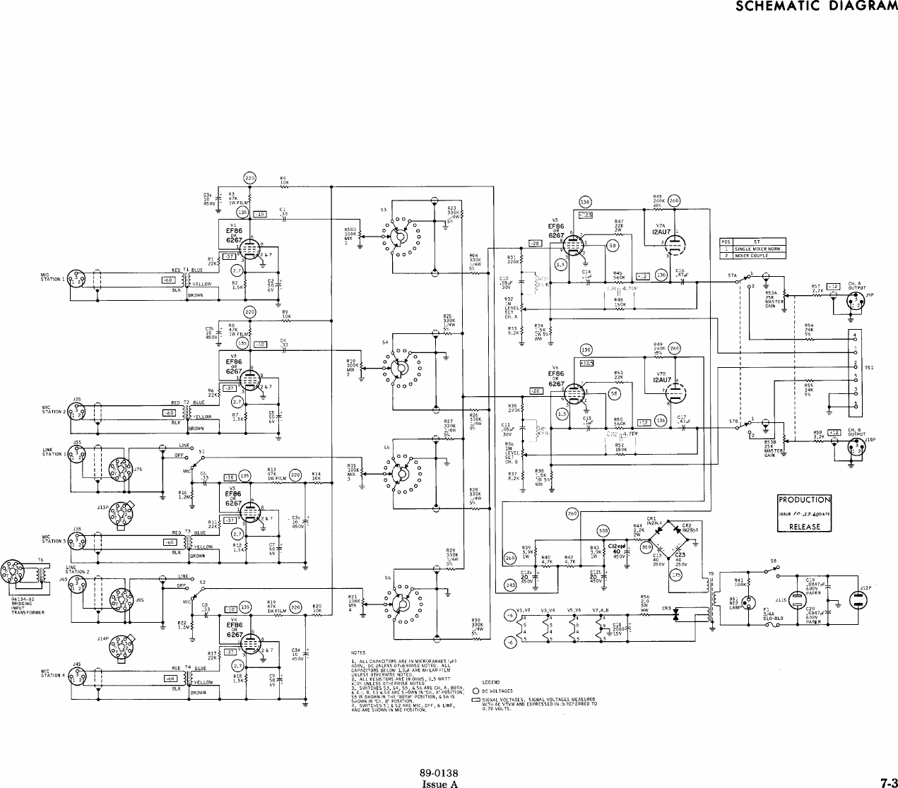
The only doc I have is a pdf I found on the net years ago. It has a rather scruffy schematic but it looks genuine.
Cheers
Ian
Attachments
Thanks Ian, I thought maybe that drawing had dropped off the face of the internet.
Interesting thanks! The cathode follower is stacked right on top of the screen grid, with bootstrapping to the pentode shield. Great find!
Interesting thanks! The cathode follower is stacked right on top of the screen grid, with bootstrapping to the pentode shield. Great find!
Last edited by a moderator:
Very interesting! I will try to simulate that circuit substituing the 12AU7 with a Mosfet à la Powerdrive.
Last edited by a moderator:
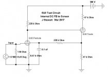
How Effective is Screen Supply Stabiliztion from Following Cathode
Curiosity drove me to do the tests a few years ago. Not much difference measured at all. The pdf covers how the work was done 🙂
Curiosity drove me to do the tests a few years ago. Not much difference measured at all. The pdf covers how the work was done 🙂
Attachments
The only doc I have is a pdf I found on the net years ago. It has a rather scruffy schematic but it looks genuine.
Cheers
Ian
The 1st triode is an elevated CF driving the 2nd triode connected as a thinly disguised Baxandall tone cct.🙂
The EF86 has DC feedback to the screen from the following CF.The only doc I have is a pdf I found on the net years ago. It has a rather scruffy schematic but it looks genuine.
Cheers
Ian
But also real Schade AC feedback to the input.
Mona


I ask myself, what is the use of that BJT in between the mosfet and the screen ??A recent circuit posted by JC Morrison in a facebook group, reportedly having almost 80dB gain!
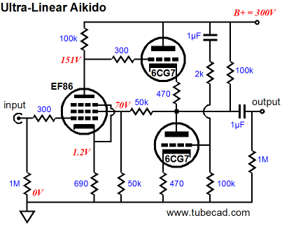
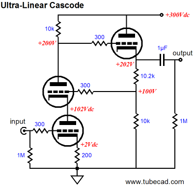
Exept those are no real UL.John Broskie in Tubecad discusses Ultra-linear line preamp.
Below are some examples.
UL has Va = Vg2 with no signal and Vg2 goes over and under Va.
Mona
- Home
- Amplifiers
- Tubes / Valves
- Gain stage with g2-feedback.