I am working on a Marantz PM7000 with many issues, most of them are already solved. But I have a problem that it is literally driving me nuts. One of the amp channel, RIGHT CHANNEL, has a very low gain.
I first focused on the input differential amp, prior to measure, I checked transistors and fixed many cold soldering. The problem remained and I began to do some measures. As I have the other channel working I did, as usual, some comparative readings and on DC I can't find any difference from the good one to the failing other. Applying a 1 Khz signal I see the signal reaching R3316 and R3314 is very low if we compare it to the 3315 and 3313 on the Left Channel. And I am a bit lost, this are the challenges I like but, at this point, I think I need some fresh ideas as mines are on a loop. I have tested voltages, as mentioned, transistors (not with a cheap transistor tester but with a wonderful LEADER LTC-906A and a modern PEAK DCA75), diodes and resistors, even some capacitors that, to my surprise, were encapsulated as a resistor. First time I see this. The feedback is OK, power supply and limiting-protection resistors, everything is just fine.
Also, I didn't say it earlier, the signal reaching both channel inputs has the same level. I want to say this in case some may think I have any issues on tone or volume control, this is already fixed (there were some problems before)
I look forward for your experience and ideas because mine are exhausted. Thanks in advance
Attachments

Dear anatech:
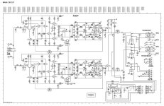
Thanks for your reply and support. Not only I checked it already, it was a bit low on capacity but with a slightly high ESR so I replaced it and the problem is already there. I like to analyse, as far as my knowledge allows, the circuits and there are many things I can't understand on these diagram, one of them is the function of C2268 right after the BIAS transistor and the next stage.
Also, something I didn't mention but I believe is relevant, there is no distortion, there is a gain difference but both channels keep the signal with the perfect shape.
I enclose a better copy of the schematics for future references.
Again, thank you
Attachments
Hi cqtsdss,
Thanks. I do have the manual.
Okay, lack of distortion means no circuit fault, just low gain. Your signal levels on each side of the diff pair will be very similar. The only reason you could have low gain in the amplifier is the feedback divider network. There is no DC servo that could pass all signals, so you must have a problem with the series feedback elements, or the passive leg that attenuates the signal.
We are assuming the amplifiers are receiving the same amplitude signal at the input.
A fault in the Vas would probably lead to DC offset and high distortion plus an unbalanced diff pair (trying to correct). We keep coming back the the voltage divider. Have you checked the resistance to common from capacitor(resistor side)? From the capacitor to the node at the transistor base? Then the resistance from the transistor base to he output?
When you see something that shouldn't be possible, it is always something simple we are missing. We discounted it as a possibility, but we need to prove everything.
-Chris
Dear Chris, Thanks again. I am out of the shop today. Tomorrow I'll check all that possible points of failure and let you know. In case I don't succeed I'll add the schematics with DC voltages and signals. Again, thank you.
And, yes (I forgot) signal in both channels is the same in all terms.
And, yes (I forgot) signal in both channels is the same in all terms.
Hi, at which points ac input signals are equals between right and left channels? In schematic, there is a connector on the left, after it signals reaches differential pair bases through another two components in series, also there's 27k resistors to ground in each channel. So are are the 1khz signals equal in amplitude at 7251 and 7252 bases ,not at connector? If so, then problem is with gain is related to feedback. If signals equal on connector, but differs on bases, then fault is in input circuits - open resistor or dry capacitor, maybe shorted to ground input. If you can't still locate fault, try to desolder all input and feedback components and compare them out of circuit. Remember fixed friends pioneer amplifier with some gain difference between channels, found problem of feedback resistors disbalance , changed them with matched by dmm resistors and problem was gone. Maybe it's your case too. If feedback from output resistor has 5 percent higher resistance in one channel, and resistor to ground a little less ohms in same channel, problem is more noticeable. Even all resistors are in allowed tolerance.