Hi,
if you want a regulated supply of +-18Vdc then use an 18+18Vac transformer.
If you want +-15Vdc then use 15+15Vac transformer.
It's that simple.
If you already have a 16+16Vac transformer then it can be used to generate a regulated +-15Vdc or +-16Vdc or +-14Vdc.
if you want a regulated supply of +-18Vdc then use an 18+18Vac transformer.
If you want +-15Vdc then use 15+15Vac transformer.
It's that simple.
If you already have a 16+16Vac transformer then it can be used to generate a regulated +-15Vdc or +-16Vdc or +-14Vdc.
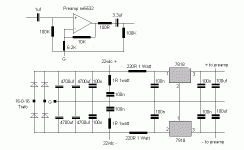
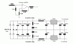
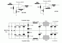
Depends on the op amp, whether a single cap between the rails (e. g. NE553x) or a cap between each rail and ground (e. g. OPAx134) is the best solution. You will need two big caps on the PCB anyhow.
Depends on the op amp, whether a single cap between the rails
If I am using NE5532 as per picture post # 22. The First config from left-side is applicable to me.
You will need two big caps on the PCB anyhow.
i.e. big caps on power supply which is on the same pcb.
Is this right ?
If the power supply is on the same PCB, you already have the big caps on it. Post #22 sounded as if the power supply with 2 x 4700 µF was off-board.
Are you really using 4700 µF following the voltage regulators?
Are you really using 4700 µF following the voltage regulators?
Are you really using 4700 µF following the voltage regulators?
Please find attached files schematic & layout.
Attachments
Power Supply Query
Today, I purchased my own digital multimeter. And I measured my system voltage. Please find my attached picture.
My transformer is 18-0-18 VAC. I measured it when not connect to my system. But when I connect to system (tda7265x5 & ne5532x3) and mains power on measured again. I found 16VAC in running condition. And if it is 16VACx1.4 = 22vdc (theory) it found 19VDC.(practical)
If it is 19VDC, and I am using 7818, 7918 for regulator then I don't need to add 220R 1 watt resistor. Is this right ? As per advice (AndrewT=if you want a regulated supply of +-18Vdc then use an 18+18Vac transformer.)
19Vdc at the input of the regulators is far too low.
A 230:18Vac transformer should measure 18Vac when 230Vac is fed in from the mains and a resistor loads the secondary to allow the rated current to flow.
When off load, the voltage will be higher. The manufacturer will tell you the regulation. If 7% regulation, then the off load voltage will be (1+0.07) * 18 when fed from 230Vac. Expect 20Vac to 24Vac from a small 18Vac transformer.
If you measured 18Vac off load then you probably have a 15Vac transformer. This would be good for a 12Vdc or 15Vdc regulated supply.
Last edited:
subwoofer preamp query
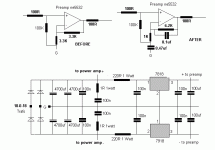
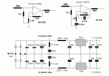
As per attached picture. I used this (BEFORE) preamp for my subwoofer. I found loudness was poor. I increased gain as 6.2K + 1K. Loudness increased to good level and I added 0.47uf cap to reduce speaker over excursion. With is all change I found NOISE also increased. Then, I added 0.1uf cap. Now noise is acceptable to me.
Now, the question is, updated preamp (AFTER) is it right ?
Attachments
Hi,
something is seriously wrong.
A 5532 is already compensated for unity gain. It should not need further compensation (the extra 100nF in the feedback loop) to be stable.
The original gain was 1+3.3/3.3 = 2 = +6dB
The new gain is 1+6.2/1 = 7.2 = +17.15dB
That is 11.15dB of extra gain. Yes it will sound louder!
the schematic is wrong.
The 100k should be connected to the signal return and to the BOTTOM of the DC blocker (470nF).
The high pass filter operating inside the NFB loop is set to 340Hz.
That will remove most of the bass signal.
That is the wrong place to filter out the bass signal.
Either the input of the amp or the output of the amp is a far better place to locate your response shaping filters.
You have no low pass filter at the input of the amplifier. Fit one!!!!!
Pra,
you need to go back to some very basic explanations of audio reproduction and understand the concepts, then move in small steps to building electronic circuits, building up knowledge on how and why they work, before trying to design a pre-amp.
Last edited:
You have no low pass filter at the input of the amplifier. Fit one!!!!!
My 5.1 DVD player's out is SUB-Low passed filter. I am going to cut-off very low frequency.
As per picture post # 33, I was using left schematic and updated to as right schematic. Now I am using only one right-sided updated schematic.
That is the wrong place to filter out the bass signal.
Either the input of the amp or the output of the amp is a far better place to locate your response shaping filters.
Yes sir, I removed added caps. And I should have to plan again for cut-off very low-frequency.
Thank you sir, for your fast help.
Attachments
- Status
- Not open for further replies.
- Home
- Amplifiers
- Chip Amps
- Gain, Preamp, Efficient Driver

