I have used Dalbani a lot for my semis. They are reliable, quick, cheap, and offer good service if anything goes wrong.
They do these in min qty of 1.
I bought 20 off each recently. NPN is E grade, PNP is ungraded and as yet untested.
They do these in min qty of 1.
I bought 20 off each recently. NPN is E grade, PNP is ungraded and as yet untested.
I have an account with RS, and used to use them a lot because I got free delivery. They seem to be getting a bit expensive, and their range doesn't seem so good. I can't get on with their new website at all, so good alternative suppliers are always welcome 🙂 I've found cricklewood to be really helpful so far, but I'll give dalbani a go this time. Thanks again for the tips. I'll post my progress for future reference.
Results
Ok, so I got my results, and I did manage to dig up this: Look just before half way down the page for two tables:
It does seem to verify what I've found, but I'm going to re-do my test between about .68K and 12K
I'll post results again for future reference.
Ok, so I got my results, and I did manage to dig up this: Look just before half way down the page for two tables:
It does seem to verify what I've found, but I'm going to re-do my test between about .68K and 12K
I'll post results again for future reference.
Attachments
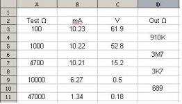
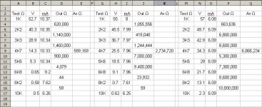
More results. This is actually quite fascinating how the CCS behaves when subjected to different loads running different currents. This is not simulated, btw. I'll post a small schematic of the simple 2 transistor circuit I'm using later on. Rail Voltage is +/- 31.5. I've got a voltmeter set over the CCS, and an array of transistors sat on the CCS output. I can then attach my ammeter to each of the pins in sequence, then read off each.
One question that does come out of this is what happens when the output current doesn't change between resistor values? I've fiddled the results somewhat because it stayed rock solid on 6.09mA. Each of the equations in the P column alternately adds and subtracts .001. If I leave the values the same, I obviously end up with a divide by 0 error, and this would also imply infinite output impedance. It's a tricky one! Whatever I do here I'm realisticly looking at introducing a factor of ten error (or worse!). If I +/-.0001 from alternate result I end up with an average output resistance 10x what's shown. I'd like the be able to measure more accurately, but my ammeter only goes down to tenths of mA! Is this equation right? Or am I missing some major subtlety?
Also, somtimes the current doesn't always carry on a trend of going up or down, and changes direction half way through. This can sometimes change the apparent output resistance to a negative value, which screws up the average result, so signs have to be changed before summing.
Is it correct to be averaging over more than 2 values? Or should I just be looking at the one closest to a rail drop over the CCS? Sorry for the essay, but this is getting quite interesting! As always in trying to answer what might look like a simple question I'm simply generating more for myself!
If my results are correct, it looks as though LF OL gain is roughly inversely proportional to VAS current. Same rules as using a simple resistor I guess - Increase Rc to increase gain, but with a corresponding decrease in Ic.
Attachments
Interesting results!
It seems that even a simple CCS can have quite a high output impedance!
As for the negative impedance, this could be due to the fact that the CCS is no longer sourcing current but sinking it.
It seems that even a simple CCS can have quite a high output impedance!
As for the negative impedance, this could be due to the fact that the CCS is no longer sourcing current but sinking it.
ian_elvar said:More results. This is actually quite fascinating how the CCS behaves when subjected to different loads running different currents. This is not simulated, btw.
You could use a cascode device, FET or BJT, if you want a current source with high and constant output impedance.
BTW, two transistor CCS is very dependent to temperature over 45grdC. More temperature stable is the BJT-LED one.
Hi Ian,
setting your current measuring DMM to read mVdc and monitoring the Vdrop on a series resistor will improve both the accuracy and resolution of the current measurements.
If you use a 10r+-0.1% and send 10mA through it Vdrop is 100.0mV The scale on a good DMM set to a 200mV scale can also be around 0.1% of full scale. That gets 0.3% accuracy and 0.1% resolution.
Similarly, 100r for 1mA gets you to the same figures.
Now if the resistor is +-1% and DMM is +-0.5% then the accuracy drops to +-2%, but resolution remains at 0.1%.
Yes, that makes total sense. I didn't get a chance to do any fiddling over the weekend, but I'll post back my new results this evening.
roender said:
You could use a cascode device, FET or BJT, if you want a current source with high and constant output impedance.
BTW, two transistor CCS is very dependent to temperature over 45grdC. More temperature stable is the BJT-LED one.
I had thought about a cascode, but wont it limit the +ve swing a little bit?
Hello Ian,
There is no such thing as a free lunch.
You will trade output voltage swing for accuracy and precision.
Mihai
There is no such thing as a free lunch.
You will trade output voltage swing for accuracy and precision.
Mihai
roender said:Hello Ian,
There is no such thing as a free lunch.
You will trade output voltage swing for accuracy and precision.
Mihai
Lol. Point taken. I'll give it a go and see how it turns out.
No progress on current source measurements yet, but I got my new bjts from Dalbani. The 1381's are E rated too, all being 130-150 hfe. The 3503's are about the same spread, which is encouraging.
by the way...
Have you heard any difference, from a sonic point of view, between the "normal" CCS and the cascoded one?
Have you heard any difference, from a sonic point of view, between the "normal" CCS and the cascoded one?
I must confess I'm not a great believer in circuits having a particular 'sound'. If it measures better somehow then I'm always game for experimentation, but I'm afraid I've yet to find anyone that can convince me that listening tests can result in anything very meaningful.
Hi all, I'm new here.
IMHO:
For good CCS is concerned, we need to look for tran. with characteristic of
1) minimal current variation for wide range of Vce (or Vds) for a given base current (or gate voltage). Hence, output graph shows extremely flat Ic (Id) vs. Vce (Vds) curves. POST #8 ?
2) small Beta (or transconductance) at the Iq.
3) Emitter (or source) regen. R should be as large as the available bias voltage allowed.
Those 3 will secure a very solid current source. Good ones should be in the order of well above 10 megaOhm.
FIY, I've never empirically tested these ideas. I would appreciate corrections and constructive inputs.
if you need more precise measurements of current, put a 100 or 1k resistor in series with the CS and measure the voltage drop across it. the 100 ohm resistor will give you 0.1v/mA and the 1k will gve you 1V/ma. since the CS is such a high impedance, the series resistor for current measurement shouldn't introduce a large enough error to be concerned with. using the 1k resistor will give you a measurement capability down to the microamp level (assuming that your meter can read millivolts). you will improve the accuracy of the measurement if you use a 1% tolerance resistor or you can make a 1% tolerance resistor by paralleling 10 10% resistors of 10 times the required resistance(i.e. 10 10k 10% resistors in parallel= a 1k 1% resistor, but you should verify the final resistance anyway).
unclejed613 said:if you need more precise measurements of current, put a 100 or 1k resistor in series with the CS and measure the voltage drop across it. the 100 ohm resistor will give you 0.1v/mA and the 1k will gve you 1V/ma. since the CS is such a high impedance, the series resistor for current measurement shouldn't introduce a large enough error to be concerned with. using the 1k resistor will give you a measurement capability down to the microamp level (assuming that your meter can read millivolts). you will improve the accuracy of the measurement if you use a 1% tolerance resistor or you can make a 1% tolerance resistor by paralleling 10 10% resistors of 10 times the required resistance(i.e. 10 10k 10% resistors in parallel= a 1k 1% resistor, but you should verify the final resistance anyway).
Thanks
 I was looking at doing something along those lines, but not got round to it yet. I'll post results as soon as I get a bit of time. I've got some precision resistors hanging around somewhere, but I'll measure whichever I actually use anyway to get a calibration.
 diy_Qui, thanks, I'll have a look through my stock of transistors and see what I've got that fits that set of requirements the best, then see what comes of my experimentation.
Have you simulated at all? I've just sat down in front of LTspice today, and I'm slowly getting the hang of it. Maybe I'll try when I'm a little more confident with it.
you cannot improve the accuracy of a 10% resistor by simply paralleling them.unclejed613 said:you will improve the accuracy of the measurement if you use a 1% tolerance resistor or you can make a 1% tolerance resistor by paralleling 10 10% resistors of 10 times the required resistance(i.e. 10 10k 10% resistors in parallel= a 1k 1% resistor, but you should verify the final resistance anyway).
Selecting using an accurately calibrated measuring system can get much more accuracy.
Hi Ian
In the equation you are using the Rc is limited by the parallel equivalent of the VAS stage and the load. Effective output resistances of CE stages may be in the region of a few 100 k. BUt if you have an output transistor and driver transistor with an 8 ohm load, the Rc load will be about 8 x100 x100 = 80k
Remember these figures are all "small signal" equivalents. You can achieve a high Rc by cascoding but you still have the output load...
cheers
John
ian_elvar said:
diy_Qui, thanks, I'll have a look through my stock of transistors and see what I've got that fits that set of requirements the best, then see what comes of my experimentation.
Have you simulated at all? I've just sat down in front of LTspice today, and I'm slowly getting the hang of it. Maybe I'll try when I'm a little more confident with it.
I played with SPICE briefly, years ago, but recently i started poking around with the basics (ONLY) in Multisim. It's very good. The aggravating things about simulations is that the device I like to use is not in the library even though, say, Multisim has over 20000 models. Also, they are just for spotting our mistakes (or incompetence) circuit designs. The detailed accuracy is not there, IMHO. For an example, 2SD1609 I suspect perform a lot better than 2SC2240 as a gain device, regarding THD. But simulation will not give us that. The models are just not detailed enough, IMHO.
- Status
- Not open for further replies.
- Home
- Amplifiers
- Solid State
- Gain calculations