In attachment you can find the datasheets of the different names given to basically the same tube (pdf files), plus (jpg files) curves of it at different positive g3 voltages (curves square up and the screen current decreases).I have never seen a GU50 so I have no real experience with them. What are you trying to do with it? Can you post a data sheet?
I would like to build a push pull amp with a sextet of them. Now the best attempt (on LTSpice) is to apply 20% UL with a tertiary winding for screens, and supply the PI from those UL taps to give shunt feedback to GU50s' g1 through power drive (à la Baby Huey) going into AB2. No gnfb, but a small amount of variable current feedback from OT secondary tap to PI.
Your solution would simplify the power supply (no more need to have +-3 times the bias to supply the powerdrive) and the output transformer as well (no more need for tertiary winding), so will reduce the cost of this "experiment".
Thanks
PS
this is the LTSpice model I use:
Code:
*
*
* Generic pentode model: GU50
* Copyright 2003--2008 by Ayumi Nakabayashi, All rights reserved.
* Version 3.10, Generated on Thu Dec 23 17:30:30 2014
*               Plate
*               | Screen Grid
*               | |  Control Grid
*               | |  |  Cathode
*               | |  |  |
.SUBCKT GU50 A G2 G1 K
BGG   GG   0 V=V(G1,K)+1
BM1   M1   0 V=(0.10436355*(URAMP(V(G2,K))+1e-10))**-0.94152046
BM2   M2   0 V=(0.61437126*(URAMP(V(GG)+URAMP(V(G2,K))/3.6950521)))**2.4415205
BP    P    0 V=0.0013346082*(URAMP(V(GG)+URAMP(V(G2,K))/6.0143635))**1.5
BIK   IK   0 V=U(V(GG))*V(P)+(1-U(V(GG)))*0.00086083603*V(M1)*V(M2)
BIG   IG   0 V=0.000667**408*URAMP(V(G1,K))**1.5*(URAMP(V(G1,K))/(URAMP(V(A,K))+URAMP(V(G1,K)))*1.2+0.4)
BIK2  IK2  0 V=V(IK,IG)*(1-0.4*(EXP(-URAMP(V(A,K))/URAMP(V(G2,K))*15)-EXP(-15)))
BIG2T IG2T 0 V=V(IK2)*(0.952380952*(1-URAMP(V(A,K))/(URAMP(V(A,K))+10))**1.5+0.047619048)
BIK3  IK3  0 V=V(IK2)*(URAMP(V(A,K))+11100)/(URAMP(V(G2,K))+11100)
BIK4  IK4  0 V=V(IK3)-URAMP(V(IK3)-(0.0010136338*(URAMP(V(A,K))+URAMP(URAMP(V(G2,K))-URAMP(V(A,K))))**1.5))
BIP   IP   0 V=URAMP(V(IK4,IG2T)-URAMP(V(IK4,IG2T)-(0.0010136338*URAMP(V(A,K))**1.5)))
BIAK  A    K I=V(IP)+1e-10*V(A,K)
BIG2  G2   K I=URAMP(V(IK4,IP))
BIGK  G1   K I=V(IG)
* CAPS
CGA   G1  A  0.1p
CGK   G1  K  8.4p
C12   G1  G2 5.6p
CAK   A   K  9.2p
.ENDS
Attachments
-
EL152.pdf239.4 KB · Views: 179
-
Pentode GU-50. Specifications.pdf185.3 KB · Views: 324
-
 gu-50_g2-250v_g3-0v_100.gif16.3 KB · Views: 190
 -
 gu-50_g2-250v_100_g3-30_g2.gif16.8 KB · Views: 623
 -
 gu-50_g2-250v_100_g3-30.gif16.3 KB · Views: 620
 -
 gu-50_g2-250v_100_g3-10_g2.gif16.2 KB · Views: 619
 -
 gu-50_g2-250v_100_g3-10.gif16.2 KB · Views: 618
 -
 gu-50_g2-250v_100_g2.gif16.1 KB · Views: 637
 -
LS50.pdf731.3 KB · Views: 172
-
GU50.pdf158 KB · Views: 175
Last edited:
Hi,
Just found this diagram in the Japanese schematics and designs published today on this forum.
I guess it could be used too for using the ultralinear tap to feed G2 with a somewhat lower voltage than B+. For example use a KT88 with 560 VDC B+ and 400 VDC for G2. G2 could still follow the plate’s swing.
Has anyone tried this ore something similar? What can be expected?
Regards, Gerrit
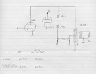
Here is my look at that circuit, circa 1960 before HV FETs were available. Amazingly still in an old file. Tried all loose wired on the test bench, it worked. But at that point I moved on to other things.🙂
Attachments
Yes, he stated many times that he uses them with 850V on plates, 270V on screens, +15V on g3, shunt feedback, and screens connected with a low dynamic impedance to the cathode. He gets around 100 Wrms from a pair of them.the GU50 [omissis] Anatoliy aka waveboure made such an amp....running plates at 800 vdc...
Ok, so I've done some more simulations and with the sextet of GU50s set-up with: plates at 900V, screens at 300V, grids supplied through a voltage divider 330k 33k from plates to ground, p-mosfet on cathodes with -103V bias, Raa 2k4 circa, PI with CCS on cathodes. I obtain around 450W with 2% THD (I've some positive current feedback from the speaker to the PI). Wow!
George, While your at it ..... another circuit to try from Graham Dicker. Worked really well for me.
Ejam
I'm interested because I have got a large stash of PL36 (EL36 with 25V heater). See EL36: Applications in Audio and search for "EL36 in grounded grid mode". However, I understand this "grounded grid mode" is not equivalent to the UNSET drive, or do I miss something ?
George
While your at it ..... another circuit to try from Graham Dicker. Worked really well for me.
Regards
Ejam
Hi Ejam, What is the RdL device between the plate and screen? Is it just a resistor or a inductor? Can you show the full schematic of the amplifier? I am interested in trying it out.
- Home
- Amplifiers
- Tubes / Valves
- G2 using MOSFET ultralinear feed