I'll be listening for the News: "Fireball envelops South Florida"
Not today. I was hoping for some rain yesterday so I would have an excuse to play with some electricity (safely inside the house). About 5AM this morning I was awakened by some serious thunder and lightning. When I left the house this morning the streets were flooded over and hail was popping off the winshield. I guess we went from winter to summer overnight!
If you want some cheap 6BQ6GAs, I've got a box of them (40 or 50) from the last tube sale
I think that I have caught my limit on those guys. I got two batches from AES when they were 98 cents each. Then vacuumtubes.net had them by the box full for 65 cents each so I bought a box. Some of the AES tubes are obviously bad, so they may become firebottles.
I have never understood the popularity of ultralinear. By the time you add enough NFB to get a decent output resistance you can consider a number of other options like local Schade feedback *instead*. I suppose I need to read H&K again ... or not ;-)
It looks different, and audiophools like that sort of thing, and even come up with considerable "folk wisdom" as to its supposedly "magical" properties. UL is just another form of local NFB. Since all my work has been with types like the 807 and the horizontal deflection finals that like to see low screen voltages, UL just won't work. For 807s, I used the usual form of parallel local NFB: from plates back to the grid drivers (what's since come to be called "Schade feedback" here). The 6BQ6GTBs didn't require the extra help to clean 'em up, and a modest amount of gNFB was all that this type required to sound really good.
Doesn't mean that I would never consider it, it's just that it hasn't come up as a design possibility just yet.
@Anatoliy: I have never understood the popularity of ultralinear. By the time you add enough NFB to get a decent output resistance you can consider a number of other options like local Schade feedback *instead*. I suppose I need to read H&K again ... or not ;-)
I share your opinion, Michael!
I'm going to try a positive FB on the 3'rd grid of GU-50 (in addition to a negative feedback to the 1'st grid)
UL? UseLess?
Couple of things that bother me about UL mode. The most obvious problem is that the tube's current capability drops off just when you need it most. Then there is screen current distortion in spades when plate V drops below screen V. A separate screen winding or Fet driver at lowered DC voltage could fix the second problem.
But I suspect that the compressive screen current distortion is being played off against normal expansive 3/2 power distortion in the usual tapped xfmr designs. Even then, the 3/2 power distortion is plate current related, while screen current dist. is plate voltage related. Maybe this is OK if it's tuned up for a resistive load, but a reactive load (speaker) makes them go out of phase with each other.
Then the usual xfmr tapping arrangement won't even work readily for a "sweep" tube. (sound of Axe falling)
I'll be listening for the News: "Fireball envelops South Florida"
Well, one of the local TV stations has been running teaser commercials to get you to watch the 11PM news. They have been showing a rather large fireball that somebody taped while driving down I-95. Not me though, I'm 10 miles west of I-95. The fireball was related to a tornado and some power lines.
On a much smaller scale, I got a wild idea, wired 4 $1 tubes together with no coupling caps. It looked cool, until I turned it on. Then one tube turned red, and a resistor fried in half. Game over for tonight. May have time tomorrow night.
I just realized 6BQ6s are basically a dollar. Where have I been? How can I resist...? It would make a nice 30W per channel amp for next to nothing in tubes. Scaled drive would be in the same 60-80V range as with the 6DQ6
Been there; done that. I'm getting better than 37W from a PP pair of Class AB1 6BQ6s (both the slim 6BQ6GTB and the fatter 6BQ6GA). I also discovered that these sound really good as well. They're like a 6V6 on steroids. I run mine with a bias current of 50mA / phase (17.5W of Pd -- 12W rated). That gets them more towards Class A operation, and definitely improves the sonics. Since these were intended for the more demanding horizontal deflection duty, busting the Pd spec doesn't result in red plates, nor does it have much impact on service life in the much less demanding audio final use.
I went ahead and got a 50 pack myself before these get expensive because we keep talking 'em up as audio VTs.
I just realized 6BQ6s are basically a dollar. Where have I been?
These were the tubes that I learned on. In the late 60's you could find these and 6DQ6's by the handfuls at the local trash dump, inside all the discarded black and white TV sets. Transformers, octal sockets, and all the other parts were free too. 6L6 types were very rare in the dump but 6V6's could be found if you knew the magic word, "Magnavox". I came to the conclusion that the 6V6 wasn't much fun because they died too easy at the hands of a teenage amp maker that didn't understand the meanings of things like "bias" "load line" or "impedance".
Now I have over a hundred 6BQ6's all purchased at under a buck. When I first got some I did some tests. Pictures are in the "tube sale at AES" thread, posts # 127 and 128.
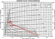
Observations discovered somewhere else in that thread (or maybe another one) found the limits of screen drive. As the screen is driven positive the plate is heading toward zero. When the plate voltage goes low enough and the screen voltage is high enough the screen will draw a lot of current, enough to cause it to glow brightly. As the plate voltage begins to return to a high positive voltage, that glowing screen grid will emit electrons that will travel to that positive plate resulting in a nuclear fireball inside the tube and lots of blown components! Dual grid drive may allow for more power without such bothersome side effects.
http://www.diyaudio.com/forums/tubes-valves/128533-tube-sale-aes.html?highlight=tube+sale+aes
Note the observations I made in post #146. I found that the best distortion characteristics in screen drive could be obtained with G2 idling at +80 volts and G1 idling at -19 volts. Given these conditions it would seem that you could drive both grids with G1 remaining entirely in the negative voltage region. This could lead to a very simple directly coupled circuit.
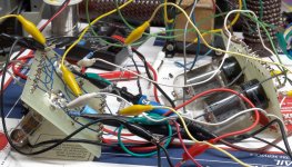
Last night I created a furball of clip leads and tag boards in about 1 hour. I powered it up and got some glow and some smoke. I flipped the master kill switch and left the room.
Today I got home from work late and turned on the TV to get my weekly fix of Lost. During a commercial I discovered last nights blonde moment. The negative power supply was turned off....DOH. Of course things got hot.
So, tonight I tried again.....and the furball makes 40 watts at 4% distortion without any feedback or coupling caps. The only sand is a CCS in the tail of the LTP. All with 360 volts of B+. Dialing back the drive gets 0.9% at 5 watts.
All is not perfect yet since the power goes down if I crank the B+ any higher, and stability goes away over 400 volts. Still, not bad for an hours work and it proves the viability of "Dual Drive". The output tubes are 6BQ6GA's and the input tubes are 6LQ8's although just about any pin compatible that I tried worked to one degree or another.
No more time tonight. More experiments at an unknown later date, and of course I need to trace out just what I made and draw a schematic.
Attachments
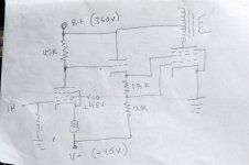
OK, here is the 5 minute simplfied schematic. This is half of the circuit since it is a push pull amp. There two of these circuits. Grid and screen stoppers (1K) are present on the input tube. There are none on the output tubes. The screens of the input tubes are tied together. There is a balance pot (200 ohm) feeding each cathode from the CCS. The grid of the input tube that is not shown is grounded through the stopper.
This can be viewed as a place to start for experimentation. It is not a "build it and it will work" circuit. At work we would call this a "proof of concept".
This can be viewed as a place to start for experimentation. It is not a "build it and it will work" circuit. At work we would call this a "proof of concept".
Attachments
I just realized 6BQ6s are basically a dollar. Where have I been? How can I resist...? It would make a nice 30W per channel amp for next to nothing in tubes. Scaled drive would be in the same 60-80V range as with the 6DQ6
AES apparently has exactly ONE 6BQ6GTB in stock (orderable)


12BQ6's in both the GT and GA flavor are on the dollar menu at ESRC. The web site says that the sale is over tomorrow. Stan usually changes the list (yeah we made the 6GV5's go away) and re posts it in a week or two. I don't think the 12BQ6's will go off the list (he has zillions of them) but I couldn't get him to match AES (98 cents) or RES (66 cents) on 6BQ6 price. He would do $2 each if I bought 100 (I didn't). At least he gurantees his tubes. AES might, but who is going to pay postage to send back a 98 cent tube. Theirs were about 10% bad, and some were obviously used.
Nothing says that you have to use the 'BQ6. I just happen to wind up with a bunch of these cheap, so they are my go to tube for experiments that are likely to end badly! I really got to crank up some of those $1 6JD5's.
Nothing says that you have to use the 'BQ6. I just happen to wind up with a bunch of these cheap, so they are my go to tube for experiments that are likely to end badly! I really got to crank up some of those $1 6JD5's.
Last edited:
I bought a bunch of tubes of Stan's dollar menu a while back. He let me buy all the same brand and none were used or obviously bad. Not bad for a buck each.
I see. Whoever dies with the most NOS tubes wins ;-)
Maybe I'll just use some new production EL34s or 6550s or something.
Oh I forgot... The screen drive voltages would be way too high on anything but sweep tubes. I'll stick with the $5-10 sweep tubes for this project I guess. I think there are still some 12AV5s cheap ... DOH!
Actually there seem to be plenty of types available for $3-$5 or a little more so no worries. Since I'm only buying 6 or 8 at a time I think I can afford it.
Michael
Last edited:
Oh I forgot... The screen drive voltages would be way too high on anything but sweep tubes.
Add here linear amp tubes, like GU-50 and 6P15P
If you die with a bunch of NOS tubes, that means you weren't working hard enough - they should be in amplifiers. Fanatics like George are a special case, as not everyone has a warehouse full..
This looks interesting so I printed out the whole thread for perusal during lunch breaks and we'll see if I can get my head around it. The original schematic has so many other fancy things in it for the PI etc that I had trouble grasping the basic idea. George's drawing in post 30 however I think clears up the basic gist of the thing. It appears that the idea is to drive both G1 and G2 with a larger AC signal going to G2 and also using fixed bias to bias G1 lower than G2.
Is that it basically? Is self biasing a possibility on something like this?
mike
Is that it basically? Is self biasing a possibility on something like this?
mike
This looks interesting so I printed out the whole thread for perusal during lunch breaks and we'll see if I can get my head around it. The original schematic has so many other fancy things in it for the PI etc that I had trouble grasping the basic idea. George's drawing in post 30 however I think clears up the basic gist of the thing. It appears that the idea is to drive both G1 and G2 with a larger AC signal going to G2 and also using fixed bias to bias G1 lower than G2.
Is that it basically? Is self biasing a possibility on something like this?
mike
That's pretty much it. It's probably reasonable to start with a ratio if G2/G1 voltage approximately equal to the G2/G1 mu factor. Sone of the reasoning behind that is in the thread I linked to at the beginning.
It's going to take a little experimentation to see if there's a preferred offset between G2 and G1 at idle. I don't think the SPICE models are going to be much help in this mode with low G2 voltage and current on both grids.
G1 current will be substantial (~100mA peak), so my strawman design has a MOSFET follower off the voltage divider to drive G1. The SRPP-like gm-followers in the driver anode circuit are for driving the G2 with low impedance, but any low impedance follower arrangement would work as well.
I don't consider this a candidate for self-bias due to the low current idle point and near class B operation. On the other hand, the gm is sufficiently low when driving G2 and G1 together that fixed voltage bias should be stable enough. Also I only need a small positive bias voltage wrt the cathode (~20V) so can generate it with adequate stability using depletion mode MOSFET and a resistor.
The total peak grid current on each side could be 150mA or more summed into the cathode, so I am using a separate stacked supply returned to the output common cathodes to drive the grids and create a small local current loop. The supply stacked under the output cathodes only sees the fixed current through the LTP set by the tail CCS.
There is a lot of stuff for sure, but I'm trying to carry the design forward into a more or less practical amplifier. I could replace the MOSFET in the LTP with another pentode, simplify the driver screen circuit and maybe even go with partial feedback and anode resistors in the drivers. I could also cap couple the driver, but I think I would still need 4 followers per channel and a negative supply for their sources.
I'm not even sure about the advantage over tetrode mode, assuming both are using plate-grid feedback. Combination drive is more linear but there is a lower gm to start with. One may be able to get higher peak current but some of the cathode margin gets used by G1 current. I do see an advantage over G2-only drive, in that approximately 1/2 the drive swing is needed.
Tubes with higher gm and lower G2/G1 mu are more suitable, just as wiith G2 drive. Don't need a regulated screen supply, but there is the extra drive difficulty.
As always a tradeoff but it looks like a fun way to build a higher power amp.
Cheers,
Michael
It appears that the idea is to drive both G1 and G2 with a larger AC signal going to G2 and also using fixed bias to bias G1 lower than G2.
Let me explain a bit. I started experimenting with screen drive a few years ago as a way to increase circuit efficiency without undue distortion. Higher efficiency can lead to big power output from small tubes.
While I also use LT spice to simulate tube circuits in order to find out if a circuit has a chance before building it, I tend to prototype and test my ideas before believing in them. It was during one of these testing sessions that I discovered the fatal limitation of screen drive. As the screen is driven positive to increase current through the tube the plate is pulled in a negative direction toward the cathode. On signal peaks I have measured +25 volts on the plate and +300 volts on the screen. At this instant the screen current will skyrocket severely overdissipating the screen grid. This may not be an issue on typical music since these peaks are few and far between. It is a big problem when the big dumb blonde one attempts to extract 125 watts from a pair of 6BQ6's. During extended full puwer operation the screen grid will glow brightly. It is hot enough to act like a cathode and emit electrons. These electrons will travel to the plate during the other half cycle when the plate has 600 volts on it and the screen is near zero or negative. There is nothing to impede this flow, so a runaway occurs blowing up the tube and the screen drive circuit. So we need a better way to crank a tube hard.....
I remembered a circuit from the 1940's that used a pair of 807's to generate about 100 watts by driving both grids. The circuit was real simple using a driver transformer to feed both screen grids, with a resistor from each screen to the control grid. So, G1 = G2 drive is not new. What is new are methods of feeding current into G2 like mosfets. The circuit I posted was intended to illustrate and prove the concept of driving both grids. I also used it to prove that schade type feedback works very well to lower the high output impedance that G1 = G2 drive provides. While the circuit does work I made it out of a pentode driver experiment that was intended to prove out some discoveries that I made while playing with Petes red board. My future experiments along these lines will use mosfets for G2 drive and maybe even G1 drive.
I made G1 stay negative for this experiment because I wanted something that I could make quickly, and I didn't use any mosfets. I imagine that every output tube behaves a little different when missapplied like this, so I can imagine that some would benefit from G1 seeing positive excursions. This would allow a lower voltage on G2 to avoid "avalanche meltdown". My next experiments will use seperate mosfets for G1 and G2 with DC and AC voltages independently adjustable. That way I can find out what works the best, then think about how to implement it.
Is self biasing a possibility on something like this?
I won't say no, but one of the advantages of screen drive is the ability to run a very low idle current. Since the idle and full signal currents may vary by a 10:1 range or more, cathode bias using the typical resistor and cap won't work. Maybe a box full of LED's or other constant voltage circuit could be used. See the end of SY's RLD thread for some new ideas along these lines.
- Status
- Not open for further replies.
- Home
- Amplifiers
- Tubes / Valves
- G1=G2/mu Scaled Drive Strawman Design