Hi All!
I picked up a used Line Magnetic LM-32 Tube DAC, and hoping to add some protective fuses to the main transformer. The DAC uses a 6X4 tube for the HV regulation, and my worry is red-plating. There is only a single fuse protecting the primary of the transformer. The cover entirely blocks view of the tubes. With the cover on, I would never know until main primary fuse blew(or smoke/smell) that there's a problem! So I want to add some fuses for protection.
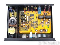
The main transformer (small EI core) has multiple secondary's. There's a 6.3V for the rectifier (1 tube), a B+ 150V winding, a 12.6V for the 12aU7 tube heaters (2 tubes), and a center tapped 16V-0-16V. A second toroid transformer has a single 8V winding (likely for the PS of the DAC chip).
So first, what rails would you fuse? It seems the voltage supply for the 6X4 cathode would be one place, but would you also protect the heater filament(s)? Would you add any protection for the 12AU7's?
The following data-sheets have the tube specs. If I understand correctly, for the 6x4, what I'm trying to protect against is runaway cathode to plate current, right? The 2 values that seem to apply are the Steady State Peak Plate Current (245 mA) and the Transient Peak Plate Current Per Plate (1.1 A at .2 seconds). For the 12 au7's, the two that seem to apply are the DC Cathode Current (20mA (per section?)) and the Peak Cathode Current (60 mA (per section?)).
Am I even looking at the right parameters? If protecting for the 12AU7's, I would multiply those values by 4 (2 tubes, 2 sections per tube), right? How would you pick a good approximation for the fuses, and would it be slow blow or fast?
This doesn't have to be done immediately (hopefully), as the tubes I'm using were graded NOS, but I don't have access to a tube tester, so have no real way of knowing actual strength of the tubes. Any help would be greatly appreciated!
I picked up a used Line Magnetic LM-32 Tube DAC, and hoping to add some protective fuses to the main transformer. The DAC uses a 6X4 tube for the HV regulation, and my worry is red-plating. There is only a single fuse protecting the primary of the transformer. The cover entirely blocks view of the tubes. With the cover on, I would never know until main primary fuse blew(or smoke/smell) that there's a problem! So I want to add some fuses for protection.
The main transformer (small EI core) has multiple secondary's. There's a 6.3V for the rectifier (1 tube), a B+ 150V winding, a 12.6V for the 12aU7 tube heaters (2 tubes), and a center tapped 16V-0-16V. A second toroid transformer has a single 8V winding (likely for the PS of the DAC chip).
So first, what rails would you fuse? It seems the voltage supply for the 6X4 cathode would be one place, but would you also protect the heater filament(s)? Would you add any protection for the 12AU7's?
The following data-sheets have the tube specs. If I understand correctly, for the 6x4, what I'm trying to protect against is runaway cathode to plate current, right? The 2 values that seem to apply are the Steady State Peak Plate Current (245 mA) and the Transient Peak Plate Current Per Plate (1.1 A at .2 seconds). For the 12 au7's, the two that seem to apply are the DC Cathode Current (20mA (per section?)) and the Peak Cathode Current (60 mA (per section?)).
Am I even looking at the right parameters? If protecting for the 12AU7's, I would multiply those values by 4 (2 tubes, 2 sections per tube), right? How would you pick a good approximation for the fuses, and would it be slow blow or fast?
This doesn't have to be done immediately (hopefully), as the tubes I'm using were graded NOS, but I don't have access to a tube tester, so have no real way of knowing actual strength of the tubes. Any help would be greatly appreciated!
Attachments
Last edited:
Does no one have an idea about this? I'm sure there is a builder in this forum who's came across the same problem. I'm investigating online all I can, but can't seem to come up with any solutions other than trial and error, or a muuuch higher level of understanding than I'm at. Surely someone can point me in the right direction?
You're seeking a solution for no problem. If the primary fuse is correctly sized it will blow before any damaged occurs, in the event of a transfromer short or some other failure. We're talking probably a total of 15mA of current at the most. I've never seen preamp tubes red plate, and the 6X4 has plenty of capacity to handle the small amount of current in the circuit. I have a DAC that runs 6 12AX7s and 2 12AT7s at the output and I've never had a problem. Literally millions of tube preamps run small signal tubes and they tend to last for years and years.
I don't know what prompted your concern, but really, there's nothing to worry about here.
I don't know what prompted your concern, but really, there's nothing to worry about here.

Hey Grovergardner! My main concern was the 6X4 tube red plating. I may have it wrong, but I've read posts that seem to suggest that is a common occurrence with 6X4 tubes. On my headphone amp, the tubes are visible, so when a 12AT7 red plated, I knew it within moments of turning the amp on, shut it down, no harm was done. This DAC doesn't leave the tubes visible, and with the main transformer having so many secondary's, I thought it would be hard to replace. I could be totally wrong, but red-plating on a rectifier tube is bad news, right? I guess I could just run the DAC with no top cover?
I'm not aware of 6x4s being problematic. But regardless, tens of thousands of enclosed tube preamps function for decades without the small signal tubes red-plating. I've never experienced or read anything about such a phenomenon, but of course it's possible. You could add a fuse to the B+ but it would need to be very small--like 20 or 30mA at the most--and you have to know the current draw of the buffer tubes to size it properly. I'd be hesitant to modify an expensive piece like that for a problem that strikes me as exceedingly rare.
As the 6X4 ages, or if a loading issue stressed that valve, then it is plausible for the 6X4 to arc from plate to cathode and effectively short the PT HT secondary - which may or may not be stressed before the primary fuse opens (the primary fuse is not likely designed to save the PT secondary from death, but rather to save your house). That risk is fairly easily mitigated by adding a 1N4007 in series with each anode of the 6X4, and looks like it can be easily implemented.
Fusing the HT secondary requires data on the PT and the loading - perhaps beyond you at the moment, but you can use the linked doc to an understanding of what would need to be considered.
https://dalmura.com.au/static/Valve amp fusing.pdf
Fusing the HT secondary requires data on the PT and the loading - perhaps beyond you at the moment, but you can use the linked doc to an understanding of what would need to be considered.
https://dalmura.com.au/static/Valve amp fusing.pdf
Hi Trobbins! So, I've read about the diode mod in other places, but does that significantly change the sound? Strangely enough, I want the sound of the tube rectifier, but I also want to protect the transformer.
I did start reading that article yesterday. Unfortunately, it seems far above my level, which is why I was posting here. I guess it wouldn't cost much to get a few fuses of each amperage in a range around the Steady State Peak Plate Current. If it blows, go up a value, if it doesn't go down a value until it does, then step 1 or 2 steps up. I can always throw a high value in until testing, would be no worse off than it is already. Might take a while to dial it in, though. HV cut off from a blown fuse shouldn't hurt anything, right?
I did start reading that article yesterday. Unfortunately, it seems far above my level, which is why I was posting here. I guess it wouldn't cost much to get a few fuses of each amperage in a range around the Steady State Peak Plate Current. If it blows, go up a value, if it doesn't go down a value until it does, then step 1 or 2 steps up. I can always throw a high value in until testing, would be no worse off than it is already. Might take a while to dial it in, though. HV cut off from a blown fuse shouldn't hurt anything, right?
Adding anything in to an amp is a risk. I wouldn't add in fuses unless I was well aware of what the outcomes could be - hence the aim of that article. Perhaps better to not go there if you do not have a good awareness, as it appears you are playing with an expensive and new item of equipment, rather than throw-away diy equipment.
The ss diode mod has been around for nearly 2 decades, and the subject of many forum threads - google is your friend for subjective views.
The ss diode mod has been around for nearly 2 decades, and the subject of many forum threads - google is your friend for subjective views.
- Home
- Amplifiers
- Tubes / Valves
- Fusing Secondary's on a Tube DAC, Need Help