I am building a very simple amp, or so I thought.
It only consists of 5AR4 -> LC -> LC -> KT88 single ended output stage (cathode biased)
The input stage is to be built on a separate chassis.
I turned on the amp without tubeI started with 630mA fuse, which blew. I increased the fuse size progressively till 1.25A, which still blew.
I checked for shorts from B+ to ground, or anywhere else to ground. None that I could find.
I got fed up and used a 10A fuse, then the power transformer smoked. Bad idea in retrospect. At the time I concluded that I had a bad power transformer.
So I replaced the power transformer. Powered it up, it worked, sort of. B+ is between 350-380V, I don’t remember exactly, transformer secondary is 420V, so seems good. One of the tube achieved 36.6V bias, seems good. The other tube wasn’t conducting, due to a loose connection.
I rectified the loose connection, and powered it up. I watched the tube bias rises to 50+V, which is very strange, and then the fuse blew.
I checked everywhere for short, but none that I could find.
I removed the tubes, fuse still blew.
Then I realised, the OPT is unloaded after I replaced the power transformer. I thought I might have fried the OPT.
I disconnected the OPT, fuse still blew.
I disconnected the second stage LC, fuse still blew.
I removed the rectifier tube, fuse did not blow. So I guess, at least the power transformer is fine.
So, there is something wrong between the 5AR4 and the first LC? The choke seems fine, no short to ground. The capacitor seems fine to me too, correct capacitance reading, no short to ground.
How else can I check if a choke is faulty?
Would faulty rectifier tube blow fuse? It lights up fine, and seems to pass current fine.
I don’t know what else to check for.
Finding treasure without a treasure map is an exercise in futility.
Please post a complete schematic of the amp and power supply.
Give the transformer voltage ratings, all the electrolytic voltage ratings, electrolytic capacitance uF values, etc.
That might be a good start.
What was the source of the amplifier design?
Look for electrolytic caps connected backwards (B+ and self bias circuits), too much input capacitance for a 5AR4, electrolytic caps with voltage ratings too low for the voltage of an unloaded B+, other wiring errors.
Last edited:
Last edited:
It has got to be either some effect due to start up surge, or a short somewhere. Do you have a dim bulb tester, to save the strain on your electronics?
And the filter capacitors are they rated at 1000V AC ?
Disconnect them just to narrow down the fault.
Disconnect them just to narrow down the fault.
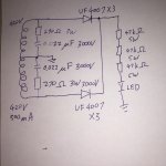
A 420 - 0 - 420 VAC secondary should provide around 550 volts of DC once rectifier and filtered. This is too much for a single 1N4007 diode, and most new production 5AR4 tubes, or KT88's to deal with.
The usual "rule of thumb" for silicon rectifiers is to rate them at 3 X the applied AC voltage, so you will need at least two UF4007's in series on that transformer. Your caps need to be rated for at least 600 volts.
My KT88 amps use a 375 - 0 - 375 volt transformer and the B+ is around 435 to 455 volts with a 5AR4, and 465 volts or more with silicon rectifiers.
the voltage across the diodes is (2*Vsec)*1.414= 1470V without load probably more than 1500V, so you need 3* 4007 in series.
I must have killed 10+ fuses today. I am running out of fuse, I need to get more fuses to do more serious experimentation. It may take a week or two.
So there are 2 possible scenarios. One is a short somewhere. The PSU is built on 2 perforated boards. If this is true, the fault can be narrowed down to the first board or on the rectifier tube socket.
Second possibility is the rectifier is not up to the task. 5AR4 datasheet cites examples with secondaries up to 550V. Of course real life does not always match theory.
With 420V secondaries, with tube rectifier and choke input, PSUD2 simulation shows about 340V output. I chose choke input over capacitor input thinking it would be easier on the tube.
Since my rectifier is shot anyway, I think I will reconsider the options, and while I am at it, might as well rebuild the first PSU board. I am also looking for commercial PCB to reduce chances of error. Recommendations are welcome.
I don't have a dim bulb tester. The transformer is rated at 600W. With no capacitor connected, it blew 630mA slow blow fuse. I've never build anything with such a large transformer, so I don't know what to expect.
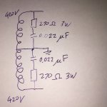
Edit: The 0.022uF capacitors above are rated at 3000V AC. LC capacitors are rated at 900V DC.
Last edited:
This link was posted on another thread considering soft start up options. The outputs that show the current drawn by a big transformer on startup are quite surprising - could be 200A in your case.
Neurochrome and soft start
Neurochrome and soft start
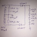
I decided to risk another precious fuse to try the 3x UF4007 idea.

The good news is the fuse did not blow.
The bad news is I was expecting 600V or so voltage, but I’m getting only 400V. This could well be half wave rectification because of bad electrical contact, but I can’t get it to go any higher. Although before the fuse blew, I seem to be getting what PSUD2 predicted.
If you don't have any smoothing capacitors (like in your picture), you won't be getting 600VThe bad news is I was expecting 600V or so voltage, but I’m getting only 400V.
You do not show a capacitor in the circuit (Rectifier positives to ground).
Your meter probably will not display the full voltage, just the average. Also the waveform is still raw DC, positive halves of the sine wave. So about 390ish volts?
Add a small 10 - 50uF capacitor and the voltage should increase to about 580 volts DC.
Same thoughts as TG...
Your meter probably will not display the full voltage, just the average. Also the waveform is still raw DC, positive halves of the sine wave. So about 390ish volts?
Add a small 10 - 50uF capacitor and the voltage should increase to about 580 volts DC.
Same thoughts as TG...
Last edited:
With solid state rectifiers (neglecting the drop of 1V or less per series rectifier):
1. Choke input; 420VAC x 0.9 = 378V
But . . . only if the choke inductance is equal to, or more than critical inductance.
Critical inductance = 350/mA load current (for 60Hz power mains, and full wave rectification).
Critical inductance = 420/mA load current (for 50Hz power mains, and full wave rectification).
When the load current is too low, or when the critical inductance is too low . . .
Then the B+ will raise by up to 420VAC x 1.414 = 594V.
Before the output tubes warm up, that is what you may get, 594V.
2. Capacitor input; 420V X 1.414 = 594V
With 594V on the first capacitor, the peak inverse voltage across the rectifier(s) is 2X 594V = 1188V.
Careful, if you use 115V primaries, and your power mains go to 120V or more, guess what, more peak inverse voltage. The same goes for 230V and series primaries, if the power mains goes to 245V . . .
For every volt more than 115V, the 420V goes up by 3.65V.
For any rectifier tube, and cap input filter, do not use a large capacitance capacitor before the choke.
Use larger capacitors after the choke.
"All Generalizations Have Exceptions" (even this generalization).
Last edited:
For any rectifier tube, and cap input filter, do not use a large capacitance capacitor before the choke.
Use larger capacitors after the choke.
a 100 uF as the first input cap on the tube rectifier, perfectly fine...
I use 100uF / 30 H / 100uF on my HV supplies.....
I get both 100uF caps inside one can, so makes the layout a little easier that way....
6A3 has a legitimate technical point while rectifiers for old school CRT TV,s were designed for large amounts of capacitance directly after the tube that is certainly not the case with many rectifier tubes .
All you need to do is check out the tube design limits of Mullard-RCA etc technical manuals even many of the later B9A based rectifiers had a design limit.
Nowadays its----"its a rectifier so I will stick a few 1000 uf on it just like a SS version " ---not if you want it to last --don't take my word on that check out tube data books by the "big boys " of quality tube manufacture , even WW tube data books show the same.
I have US hard bound data books on all things tube going back to the early 40,s including some well respected names at the time showing the capacitance limits on many rectifier tubes.
Is the limit on capacitance due to the initial surge of the capacitor charging or because of sustained ripple current?
Hello Astouffer--
The Mullard manuals have it down as -Limiting Values as well as a range of maximum values of limiting resistors applied to each Plate which depend on the 2x voltage-IE=2x350Va-RMS plus the amount of capacitance .
I have not checked the USA manuals yet but it looks like surge but obviously a limiting maximum current out is also quoted which would be sustained current.
Is the limit on capacitance due to the initial surge of the capacitor charging or because of sustained ripple current?
Case in point, I am using the EZ-81.
Well, there is no surge current... It takes a few seconds for the cathode to warm up. I can literally see the high voltage come up on my Fluke 87.
Secondly, I still see folks relating to tubes as if they are solid state.
You know what an EZ-81 is right ? Three metal plates separated by an air-gap.
Not thinking this tube would care about ripples currents....
Lastly, I've already commented on my thoughts why these data sheets written this way, but what do I know ???????????
-g
- Home
- Amplifiers
- Tubes / Valves
- Fuse keeps blowing

