Patent #5568561 should be in this catagory. It is a smart patent, and used by THAT semiconductors.
forr said:Having received so little returns about the subject of Common Mode Feedback puzzles me. I wonder if the concept is not that much known or if there is some kind of drawback when if used inside an amplifying circuit (someone should have told us).
Hi forr
I once had the same question as I was doodling circuits one day with a pencil and eraser, but there was no interest in the idea here. So I slapped together a mock up circuit, and actually was surprised to see that it did work and quite well considering the simple miller feedback and compensation used. Way out-performs the CCS loaded single VAS type circuit I played with before, with the same output stage. DC bias is very stable and it has been working for months, both channels so it's not just a fluke, spread out on a small table.😀 Now I am less doubtful. I too am kinda puzzled at the lack of interest on this in the forum. As for the CMFF...interesting. I will have to digest it a while. Thanks for the links.🙂
BTW, I am going to use the THAT340 descrete quad BJT IC in my next design.🙂
http://www.thatcorp.com/datashts/300data.pdf
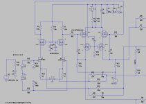
This is a old thread but maybe someone can give tips to get low distortion on this circlotron differential vas. I see it is not quite low, but on output it is -80dB.
So I do not understand it completely, maybe unbalance because of current feedback on the Jfets, I maybe need local feedback on the VAS, how?
Thanks .
regards.
So I do not understand it completely, maybe unbalance because of current feedback on the Jfets, I maybe need local feedback on the VAS, how?
Thanks .
regards.
Attachments
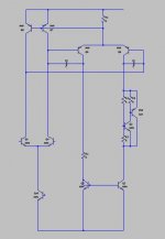
Great minds? Been thinking about this too. See image of a way that the bias current of the VAS is independent of the input diff.
Also, when the VAS is dual sided, the signal current peak is Ivas*2 instead Ivas/2, so you could save on VAS heat and maybe 2EF OPS instead of 3EF.
Others cascode the vas current mirror, but I used a resistor so that signal voltage on it allows a compensation pole of that signal path.
Also, when the VAS is dual sided, the signal current peak is Ivas*2 instead Ivas/2, so you could save on VAS heat and maybe 2EF OPS instead of 3EF.
Others cascode the vas current mirror, but I used a resistor so that signal voltage on it allows a compensation pole of that signal path.
Attachments
No I have not such great mind, these people are not save because most are in politics
Oke, I have a circlotron so I need two opposite fases, you dit post a vas for complementary output inclusive a Vbe multiplier.
But I can do use two? with a nulling ground, voltage feedback is then also possible but I do not like, I use most current feedback it prevents all kind of feedback related distortions but is dc offset unstable, for a circlotron it cancels out so here it does work fine.
Q6 and Q9 has a Cdom cap, these do put also negative feedback, special for HF.
I have use the cascode because of miller capacitances, I use a allfet amp, special here it is of benefit, yes I need higher supply voltages, but not that muchbecause of the circlotron itselfs do x2 output.
I do see much distortion on the allfet when drive hard, with low 10 watt signals it get much better, swap the circlotron itselfs from source foller to drain follower did lower distortion also, now because the circlotron itselfs do amplify making open lo0p bigger.
Most long tail pairs and voltage to current amps like the input transconductance amp can introduce distortions, there is so much readings about it, just find the right one like I have to do.
Thanks for thinking with me.
regards
Last edited:
Old 70's sansui.by making this intoThanks, Rtarbell, for your schematics. This is a very interesting discussion for me. I've sometimes seen a curious pseudo-differential stage loaded by a current mirror. The first fully differential stage I saw was the voltage stage of the JBL SA660 amplifier (1968, I think).
Hi CBS240,
I have been thinking for long of the same idea as yours It has been used in some Kaneda regulated power supplies.
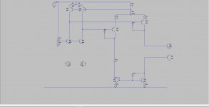
The attached image is the basic schematics in an all NPN configuration. It can't be used with a split power supply (+/gnd/-) for an outpout voltage at 0V. To achieve this, it needs additionnal circuit to refer the input voltages of the second stage to the negative power supply. An intermediate common base PNP stage with base voltage refered to the positive power supply could do it. Maybe you have some other ideas to implement a common mode loop, so my question is the same as Rtarbell : May I ask, how did you implement your CMFB?
into one of my IPS's ,it is a training ground for combo lead/lag/shunt compensation. Dumb A$$ D.self discounts this topology ,as the 20th century
Japanese ( quite perfected it) 71' sansui amp survived with a simple recap.
OS
Last edited:
Great minds? Been thinking about this too. See image of a way that the bias current of the VAS is independent of the input diff.
Also, when the VAS is dual sided, the signal current peak is Ivas*2 instead Ivas/2, so you could save on VAS heat and maybe 2EF OPS instead of 3EF.
Others cascode the vas current mirror, but I used a resistor so that signal voltage on it allows a compensation pole of that signal path.
Yes that one ive beeen playing with and have ended up using beeng well satisfied. Thou emitter resistors in all vas transistors and a pot on Q7 Q8 emitters ease the job.
Vas stability is also improoven when using base colector load to Q2 in your principle drawing.
Remember recovery and catch diodes help when overdriven.
Great minds? Been thinking about this too. See image of a way that the bias current of the VAS is independent of the input diff.
Also, when the VAS is dual sided, the signal current peak is Ivas*2 instead Ivas/2, so you could save on VAS heat and maybe 2EF OPS instead of 3EF.
Others cascode the vas current mirror, but I used a resistor so that signal voltage on it allows a compensation pole of that signal path.
Attachments
- Status
- Not open for further replies.
- Home
- Amplifiers
- Solid State
- Fully differential and pseudo-differential stages