 Wow powerbob, you ask for help which apparently you need and then you insult the members trying to help you. I'd rethink that part a bit, and I will also strongly recommend you read the forum rules before commenting further.
Only got to the second page. So maybe someone has already caught this. As soon as I saw 2 diodes creating a fullwave rectifier the bells went off. Your only using each transformer half the time. The diodes are only on for a half cycle and then only the transformer that feeds that diode is connected across the cap so only half your total voltage gets there. Get 2 more diodes and wire it properly in full wave rectification.
And actually the second textbook diagram shows it more clearly. Only half the secondary feeds the caps each half cycle, so only half the voltage. No laws broken.
Let's summarize the present situation:
The Op took two unknown transformers and found that the supposed primaries took an excessive magnetizing current.
He then connected them in series, and used the resulting composite transformer as a whole.
None of this was disclosed when the thread was first started.
The OP then connected the two secondaries in a center-tap configuration, and was surprised that the "known" theory didn't apply.
Of course, the theory that should apply is completelely different: two series transformers followed by opposite half-wave rectifiers behave in a completelely unpredictable, generally chaotic manner.
There was thus nothing reliable to be expected from such a configuration..
Add the misuse of diodes, transformer connection and suitability, in the end it is a relief something blew, making impossible the use of such a monster.
BTW, laws of physics end up reinforced by such examples: ignore them at your perils...

Let's summarize the present situation:
The Op took two unknown transformers and found that the supposed primaries took an excessive magnetizing current.
He then connected them in series, and used the resulting composite transformer as a whole.
None of this was disclosed when the thread was first started.
The OP then connected the two secondaries in a center-tap configuration, and was surprised that the "known" theory didn't apply.
Of course, the theory that should apply is completelely different: two series transformers followed by opposite half-wave rectifiers behave in a completelely unpredictable, generally chaotic manner.
There was thus nothing reliable to be expected from such a configuration..
Add the misuse of diodes, transformer connection and suitability, in the end it is a relief something blew, making impossible the use of such a monster.
BTW, laws of physics end up reinforced by such examples: ignore them at your perils...
Agreed!!
@powerbob:
When you have two separate identical transformers and you need a dual (symmetrical) supply, first build two completely separate PSUs. Then wire the outputs in series.
This way:
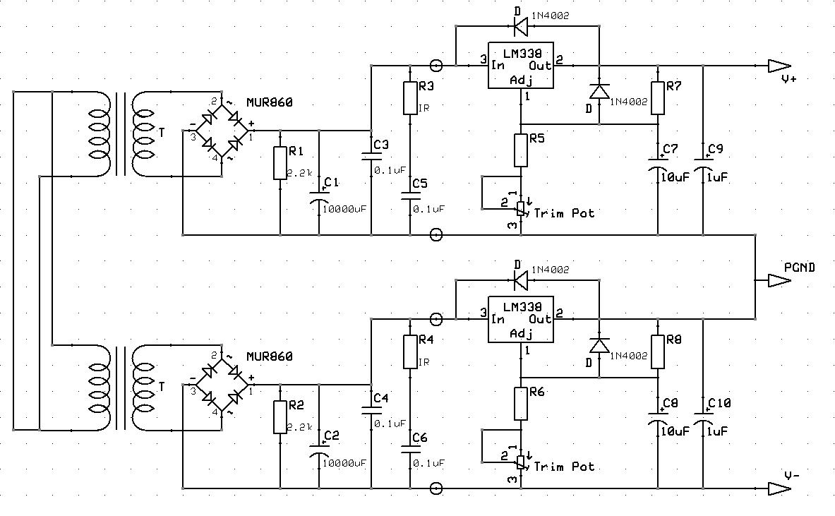
Notes to this example:
- it uses a single (dual primary) transformer with (fully separate) dual secondaries. It could have been built using two fully separate transformers instead.
- the primaries are wired in parallel implying 110-120 V mains. Think away these links between both primaries and you have a setup equivalent to two separate 110-120 V transformers.
In this example it's a regulated supply and as you can see, this way you only need one type of regulator. For unregulated supplies, the wiring of the outputs will be no different.
Component count will not increase if you substitute the two diodes for bridge rectifiers. One benefit of two separate transformers is that you don't need to connect the primaries in phase, since they're on different cores. A disadvantage: two separate "identical" transformers might be less identical than a single core dual winding transformer. When unregulated, there might be more imbalance.
Last edited:
Jitter, I only needed a single ended power supply 39vdc or less, and like most people I used what I had. The power supply worked very well for the last month. I just did not understand why the output voltage did not equal the calculated voltage. But thanks to elvees post number 14, I figured it out and as usual once you know the answer it is very simple to fix. With that said I did not have the proper transformer then and I do not have one now.
Jitter, I only needed a single ended power supply 39vdc or less, and like most people I used what I had.
I stand corrected on that one.
The power supply worked very well for the last month. I just did not understand why the output voltage did not equal the calculated voltage. But thanks to elvees post number 14, I figured it out and as usual once you know the answer it is very simple to fix.
I'm not so sure that the diodes are gone, the scope image showed the waveforms of the transformers secondaries, not the rectified waveform on the diode's cathode. The distorted waveform might have been the result of something else, especially if they weren't mains transformers.
If you still have the rectifier, you should be able to test if the junctions are still ok.
The wiring of the primaries in series probably kept things from going wrong. The drop in your power strip while the transfomers were frying (now in parallel) probably means they were drawing a lot of current. Not enough to trip your circuit breaker but enough to destroy at least one of them.
With that said I did not have the proper transformer then and I do not have one now.
And that probably was the problem all along. Even if they had been mains transformers this remark by Elvees IMO would still have been valid : "Of course, the theory that should apply is completelely different: two series transformers followed by opposite half-wave rectifiers behave in a completelely unpredictable, generally chaotic manner.".
Ironically, if you had constructed two separate PSUs by using two bridge rectifiers and then wiring the outputs in series, this problem of incorrect transformers might not have become apparent.
BTW, a dual supply can also be used single ended across V- and V+, essentially designating V- to become GND.
E.g. a -15 V 0 V +15 V symmetrical supply then becomes a 0 V +15 V +30 V supply.
And another thing: you wrote that you were floating the scope with a isolation transformer. Don't, float the device under test instead. For safety reasons. The device under test is the thing that lies there all exposed and is the biggest risk to you getting electrocuted.
Floating the scope and then connecting the probe ground to an elevated voltage or worse a Live voltage, brings all the metalwork of the scope up to that elevated/Live voltage......................
And another thing: you wrote that you were floating the scope with a isolation transformer. Don't, float the device under test instead. For safety reasons. The device under test is the thing that lies there all exposed and is the biggest risk to you getting electrocuted.
Touching the metal case of the floating scope is a serious health risk.
I imagine that might depend on the form factor and frequency of the voltage being measured and the meter itself, meaning it could go either way for the same meter... it just depends on the actual waveform being measured.
Floating the scope and then connecting the probe ground to an elevated voltage or worse a Live voltage, brings all the metalwork of the scope up to that elevated/Live voltage.
Touching the metal case of the floating scope is a serious health risk.
That is also a very good reason not to float a scope.
Today, I was also told another reason: mains filters. These have capacitors between L and PE and N and PE. If a scope is equipped with such a filter, it could bring the case to half the mains voltage if PE is left unconnected. Since these are Y-type caps, that voltage won't be lethal, but I can imagine you would feel a bit of shock nevertheless.
AndrewT, the secondary side of the power supply is isolated that is why it is safe to touch.
Then why float the scope?
Then why float the scope?
I don't think the 'scope is isolated specifically for this task. But Andrew makes a good point if it's a metal cased scope. In this case that wouldn't be a significant concern though.
Jitter i float the scope to avoid another ground path. In audio systems i notice that connecting a scope many times injects a hum in to the system. And of coarse that shows up in the waveform giving you a false reading.
Jitter i float the scope to avoid another ground path. In audio systems i notice that connecting a scope many times injects a hum in to the system. And of coarse that shows up in the waveform giving you a false reading.
What exactly do you mean by "many times"? Multiple probes?
I don't think the 'scope is isolated specifically for this task. But Andrew makes a good point if it's a metal cased scope. In this case that wouldn't be a significant concern though.
Even if it were a plastic cased scope, like many modern scopes, there still are exposed parts that are mains earth referenced (BNCs!).
My point was, when the device under test is galvanically isolated from the mains, there's no need to float the scope. The power transformer from the amp does just that, as long as you keep your measurements on the secondary side of that transformer.
But let's assume one was trouble shooting a SMPS with most of its control circuitry on the primary side. Then clipping on the scope probe ground lead could create a shortcuit that blows up a thing or two (been there, done that). IMHO, the proper way to proceed is float the DUT, never the scope, with an isolation transformer.
- Status
- Not open for further replies.
- Home
- Amplifiers
- Power Supplies
- Full wave center tapped power supply defies the laws of physics