What do you guys think about this speaker.
The height is 104.5 cm, 28cm width, depth at bottom is 45cm and 32cm at the top.
I was thinking on using a pyramid of acoustic foam inside, that is 28cm at the bottom and 85cm in height just as the picture.
I was thinking to use spike a make small ports at the base/underneath.
The volume without pyramid inside is 86liter, and with pyramid 64liter.
Picture of speaker:
Speaker - Ladda-upp.se
I think the 8" inch Full range likes 70-80 liter best, so is 64 liter a problem? If i use some wool to cover the inside, shouldnt it "make the box bigger by 10-15%? Then i could say the box is around 75 liter which i think is perfect. Does a bigger port underneath help?
What do you think about the design? Why i dont go for bigger volume is because i dont want more width then 28cm. Do you think this triangel shape is better then a completely rectangular?
The pyramid of foam, do you think 28cm is wide enough for the foam at the bottom?
My inspiration comes from the philips 9710 A5 cabinet as this one:
pag17.jpg
The Full range have approx same technical specs as l.cao 8 inch full range.
Please come with advice of what i could do better and your thought about my speaker design.
Best,
Mattias
The volume of the foam is probably negligible so your cabinet volume is close to what it is without foam. If this is a sealed box, it looks like the purpose of foam is to provide gradual damping to impedance match in order to prevent reflections much like how Nautaloss speaker works. The volume of chamber should be determined by the driver's T/S parameters. Use a program like WinISD and select sealed box and tune volume until it achieves bass extension and shape you like. The foam simply serves to prevent internal resonances and reflections without fully stuffing box. Looks interesting, it could probably be simulated in AkAbak using segments of increasing stuffing density while keeping cross section constant.
Thanks.
When i calculated on the foam, the volume is 22 liter of a pyramid thats 28cm width and 85cm in height, but you mean that its soft so it doesnt count as 22 liter? How many liter do you think the foam is in reality?
I know Zu speaker has the same pyramid in theres speaker, they said it was polythurean with open cell, so i guess its acoustic foam they use?
The specs of driver is:
Revc: 6,5 ohm
Fo: 59,150 hz
Sd: 21,382 mm
Qms: 4,284
Qes: 0,845
Qts: 0,706
Spl: 94,5
Vas: 74,785
Cms: 1,152
Mms: 6,285
I tried with winisd but maybe i got something wrong, but when i chose 50-70 liter, i get a 5db rise at 100hz, but maybe its right then, but is 5db rise at 100hz okay? Maybe you could try with these specs?
How could i calculate how big the holes should be at the base/bottom?
Dont you think a acoustic foam pyramid would be good for diffusing and absorbing?
With sealed box at 64 liter i only get 2db rise at 100hz, i choosed ported when i got 5db in winisd before, so maybe just small rectangle holes at the bottom is more then enough.
Last edited:
The void fraction of open cell polyurethane foam varies but can be as low as 2.5% for special acoustic foam to more like 10% for conventional foam. Your driver fs is 59 Hz and it has a fairly high Qts so if you design box right you should get close to 60 Hz. From picture it is a sealed box with no holes at bottom. If you made it open holes at bottom then tune it as a bass reflex but then foam would block flow as bass reflex boxes should be lined with damping at walls and not filled with foam. Yes, I do think a pyramid of foam is good for damping - clever actually.
Sorry for the picture, but the goal is to lift up the foam on 4pcs of smaller woods that the foam stands on so its like 3cm up in the air from the base so the air could flow out underneath it just as you said, and then either a quite big hole at the bottom or 4pcs of rectangle holes that is like 1,5cm in diameter and around 15-20 cm in lenght under the foams edge and with spikes at 2.5cm so the air can comes out from the base.
Which dimensions do you mean, the box or the port or both?
Maybe its better to make it not ported, but use the pyramid foam anyway.
Zu speaker model doesnt seem to have a such a big port.
This FR i think needs quite a big box, i was also thinking to make a TQWT, if i make a TQWT then i have the sizes that is optimal for this driver in TQWT, so maybe thats a much better alternative then try this pyramid foam version because i dont know how to calculate the holes etc, but maybe the pyramid speaker will sound good with the size i was thinking and with some small port slits under the base.
But i heard that TQWT can be hard to get the bass good, but TQWT version should make more bass?
The TQWT for this driver is 83 liter in volume.
Last edited:
I tried AkAbak, but it didnt start on my computer. Could you calculate on a mass loaded TL on this driver specs? As my speaker with pyramid cone inside and ported at the base/bottom? If the size of box is smaller its no problem, only better because then it dont look so bulky.
Maybe the acoustic foam could be calculated as 5liter volume because of the open cell.
Maybe the acoustic foam could be calculated as 5liter volume because of the open cell.
I tried AkAbak, but it didnt start on my computer. Could you calculate on a mass loaded TL on this driver specs? As my speaker with pyramid cone inside and ported at the base/bottom? If the size of box is smaller its no problem, only better because then it dont look so bulky.
Maybe the acoustic foam could be calculated as 5liter volume because of the open cell.
Get me the dimensions of the top (width and depth) bottom (width and depth) height overall, distance you want driver mounted from the top and your approximate vent dimensions at the bottom (cross sectional area and length of port). I will not model the foam pyramid but rather just apply stuffing damping to the lower portion. This will give you a good idea of the baseline performance and the foam can be adjusted to taste. You need a removable bottom panel to access and modify the foam pyramid though.
This actually resembles a large fat Metronome in some ways.
http://www.lencoheaven.net/forum/index.php?topic=385.45
I saw this guy used the same cabinet and with l.cao that have almost exactly the same specs as mine driver. He used the size 30cmx30cm and height 114,5cm.
I was thinking a little slimmer looking version but the same volume so i have calculated approx same but with:
28cm wide, 32cm depth and 112cm height.
He used 19mm wood, i use 18mm wood. I will use a spike ball just in height of the behind/speaker, in the middle of the speaker, a small bracing with a hole will hold the spike ball (inflatable variant, massage). So the ball will be placed just at the top of the pyramid foam you could say.
The ball will take around 1.5 liter in volume.
The pyramid i will try to custom made is 24cm at two sides and 20cm at two sides in the bottom so it will follow the shape of the cabinet and leave about a inch on each side at the base so the speaker can breath.
I will put the pyramid foam on some wood plints of 0.5-1cm in height so the pyramid dont cover the hole underneath. The hole underneath will be about 1 inch smaller then the inside dimensions so 23cmx19cm, should be around 1inch of area at each side of the base inside then? Or maybe 2inch left at the sides of the innerbase dimensions would be better? It seems in the link above that he have about 1inch left of the inside base, but i could try different by as you said have a removable base.
And was thinking 4pcs 1/8" inch , depthside holes, they would then be 28.4cm and the front/back holes 24.4cm, at the outer sides just as the guy in the link above.
This would be like a hybrid of the philips and the link above. because driver placement and height.
I was thinking to mount the center of the driver 23cm down from the top so it would center of 89cm. 112-23cm. With the spikes at bottom at about 2.5cm height the center would come in about 92cm then.
The pyramid foam would be a little rectangle shape at the bottom then to fit the cabinet shape as i wrote above. Pyramid base 24x20 and height of 89cm.
Yes its correct, i changed my mind about triangel shape, mostly because its easier to assemble the speaker with 90 degrees edges so i thought that the 32x28cm would do, or what do you think? with 28cm width the speaker wouldnt look as boxy as 30cm width so that primarly why i went with this shape also.
Maybe 26cm width and 35cm depth would be even better? with same height its almost the same volume. And then i could make the pyramid rectangle foam, even more rectangle so the foam follows the depth of 35cm. 26cm would look better visual then 28cm i think.
Maybe 26cm width and 35cm depth would be even better? with same height its almost the same volume. And then i could make the pyramid rectangle foam, even more rectangle so the foam follows the depth of 35cm. 26cm would look better visual then 28cm i think.
Last edited:
I could also get the driver with a cobalt magnet instead of ferrite.
That driver weight 5kg and the magnet has the same round shape as the feastrex, the magnet is 12cm in diameter formed like a sphere, so its also good for diffusing the soundwaves behind the speaker, and that driver also has a fo off 55 hz, and qts of 0.62. Very good Spl frequence at 95dbl, but the ferrite version also have as good Spl diagram, but a little higher fo. Do you think the cobalt version will be better? The bad thing is the freight, 5kg per driver instead of almost half that weight for the ferrite version. I just thought about the better fo and also that the big magnet diffuse good at the back. Price difference is a little more then double for the cobalt feastrex style magnet. Both are 8-inches FR.
Is it certain that the big cobalt version is better then ferrite version? Maybe the ferrite is as good and its no idea to go for cobalt version.
Yes its correct, i changed my mind about triangel shape, mostly because its easier to assemble the speaker with 90 degrees edges so i thought that the 32x28cm would do, or what do you think? with 28cm width the speaker wouldnt look as boxy as 30cm width so that primarly why i went with this shape also.
Maybe 26cm width and 35cm depth would be even better? with same height its almost the same volume. And then i could make the pyramid rectangle foam, even more rectangle so the foam follows the depth of 35cm. 26cm would look better visual then 28cm i think.
What is height of box (1 meter?) and it sounds like your circa 28cm to 32 cm dim for the width and depth is up for grabs so I will use that as a variable to optimize. Also is it OK to place the driver 20% from the top? I'm pretty booked right now but will try to model this when I have some time in next few days. I don't have any experience with fancy magnet drivers but for this application, I would guess that ferrite magnet version is fine.
The boxes i have calculate volume on is two different
Box no 1: 112 cm Height, 28cm width and 32cm depth. Approx 76l
Box no 2: 112cm Height, 26cm width and 35cm depth. Approx 75l
Its okay to change the dimensions if you find another dimension better, like lower height etc.
I dont know which design is best.
20% from the top sounds perfect.
Pyramid foam box no 1 with a base of 20cmx24cm Height 89cm
Pyramid foam box no 2 base 17x26cm
I think i will order both cobalt and ferrite version so i could try both and see if there is any difference, because i will build two speaker, one of the speaker to my relative so we will build them together. If you also could calculate on alnico version if would be very glad.
Here is the specs of the cobalt version:
Revc: 6.5ohm
Fo: 55.727
Qms:3.020
Qes: 0.780
Qts: 0.620
Spl: 94,5db
Vas: 76.472
Mms: 8.564g
Sd: 23.779mM
No problem im glad that you will look at it, thanks alot for the help.
Simulation results and proposed design
Matthtvr,
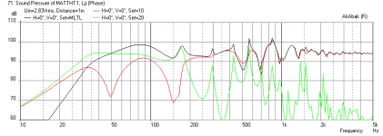
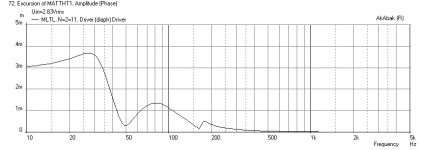
These drivers need a slightly bigger box so I increased length to 1.2m and depth is 38cm width is 28cm. The vent at the bottom is a 4 in dia hole cut in 0.75 in thick material. The speaker stands on 2 in tall feet to allow the bass to escape from the vent. You can use rectangular slots if you wish, just keep the cross sectional area about the same. The driver is located 24 cm from the top. I simulated the foam as increasing amounts of damping internally over 4 segments. It is tough to model that but I guess the bigger the pyramid of foam, the less bass amplitude you get but with smoother mids. This speaker requires floor and wall enhancement for the bass so place it about 4 in away from back wall to boost bass output and flatten response, otherwise bass will be a bit under emphasized. This design achieves a -3dB point at 42 Hz and an overall 94 dB average efficiency at 1m and 2.83V input. The design uses a 1.0 mH and 4 ohm resistor BSC circuit to flatten the rising response.
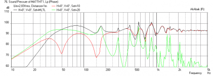
I ran the simulation with both the ferrite magnet and cobalt magnet versions. Save your money, there is very small advantage in bass extension with the cobalt version - probably not worth it IMO.
The plots are for the ferrite version: SPL vs freq., cone displacement, impedance, and last plot is the cobalt version SPL vs freq.
If you move it away from wall you will start to get cancellation dips and reduced bass extension.
Matthtvr,
These drivers need a slightly bigger box so I increased length to 1.2m and depth is 38cm width is 28cm. The vent at the bottom is a 4 in dia hole cut in 0.75 in thick material. The speaker stands on 2 in tall feet to allow the bass to escape from the vent. You can use rectangular slots if you wish, just keep the cross sectional area about the same. The driver is located 24 cm from the top. I simulated the foam as increasing amounts of damping internally over 4 segments. It is tough to model that but I guess the bigger the pyramid of foam, the less bass amplitude you get but with smoother mids. This speaker requires floor and wall enhancement for the bass so place it about 4 in away from back wall to boost bass output and flatten response, otherwise bass will be a bit under emphasized. This design achieves a -3dB point at 42 Hz and an overall 94 dB average efficiency at 1m and 2.83V input. The design uses a 1.0 mH and 4 ohm resistor BSC circuit to flatten the rising response.
I ran the simulation with both the ferrite magnet and cobalt magnet versions. Save your money, there is very small advantage in bass extension with the cobalt version - probably not worth it IMO.
The plots are for the ferrite version: SPL vs freq., cone displacement, impedance, and last plot is the cobalt version SPL vs freq.
If you move it away from wall you will start to get cancellation dips and reduced bass extension.
Attachments

Thanks alot. it will be a quite big speaker then but if thats the best then i will go for that size. I was thinking about the height, will it be worse design if the volume is kept but change height to like 103cm and width 28cm and depth 44cm? I think its the same volume then.
I will try to find 3pc of long spikes underneath then,two at the front and one at the back. but is it okay to make a extra layer 0.75 inch thick material under the bottom with the same 4 inch dia hole or will it change the ports specs? Because then i could use spikes that around 3.2cm in height. I could also make the seconds base a little bigger hole so its no 0.75in extra edge to the 4in hole.
Im a newbie on this so what do you mean with 1.0ohm, 4ohm resistor, do i need it you mean? if so which parts do i need to buy for this circuit? I have found 1.0mh part, but which awg is best? And any particular brand? or doesnt it matter? How should it be put together?
I add the Spl diagram of both Ferrite and alnico here, and as you said they behave almost identically, but i have heard that naturflex style/alnico magnet is very organic sounding and fast without clipping, saw a descrip that it was like a tube amp and ferrite as a SS amp, and also the good diffusor at the drier back/12cm big sphere magnet, but maybe it isnt worth it as the ferrite seems fine?
SPL Ferrite Alnico - Ladda-upp.se
Last edited:
Adding an additional 0.75 in thick layer will increase bass extension and decrease bass amplitude by a small amount - probably not a big deal.
A BSC is a baffle step compensation circuit. Read up on it in this forum, but basically it compensates for the loss of bass due to the sudden decrease in the front baffle size. It does this by attenuating the HF from a certain freq on up - usually 1 to 2 kHz. The circuit is a resistor and inductor wired in parallel and then the assembly is wired in series with the driver positive terminal. An air core 18 gauge wire inductor should be sufficient. The resistor needs to be a power resistor - at least 10 watts.
You can decrease height and increase volume with sides and it will be about the same performance as long as height is not drastically changed. Keep driver at 20% distance from top.
Thanks i have been searching for some inductors and found three models that seems to fit, which do you think will be best? Do you know how big the difference is of them , is 1.2/1.3mm diameter good size or which size should i look after?
Inductors
1.2MM1.0MHÔ²¹Ç¼ÜÎÞÑõÍ*¿ÕÐĵç¸Ð¡¡·ÖƵÆ÷µç¸Ð¡¡ÎÞÑõÍ*¿ÕÐÄÏßȦ-ÌÔ±¦Íø
ÒôÏì·¢ÉÕÓÑDIY±Ø±¸Ôª¼þ ³¬¸ßÐÔ¼Û±È 14ºÅ 1.0mH ÓÅÖÊÍ*²*µç¸Ð-ÌÔ±¦Íø
F-12/15·ÖƵÆ÷µç¸ÐÏßȦ1.3mmÏß¾*.1.0MH-ÌÔ±¦Íø
Resistor
ÃÀ¹ú Caddock ½ð½ÅÎ޸еç×è MS10W 100R 1K 10KµÈ-ÌÔ±¦Íø
ÃÀ¹úÔ*×°MillsÃî˹µç×è 10W 65Ôª/Ö»-ÌÔ±¦Íø
This is 50w, is it any negative to have 50w? This with one of the inductor above? Resistance tolerance 5%, is it bad?
http://www.ebay.com/itm/50W-Arcol-Aluminium-Clad-Wirewound-Resistor-4R-4ohm-/251371906775?pt=LH_DefaultDomain_0&hash=item3a86eee6d7
Which one would you choose? Or maybe no one of the above fits each other?
Last edited:
- Status
- This old topic is closed. If you want to reopen this topic, contact a moderator using the "Report Post" button.
- Home
- Loudspeakers
- Full Range
- Full Range Triangular Shape with pyramid