An lm3886 giving max 240watt/25 < 10 watt needs very little cooling. So the advantage is that you spread the heat dissipating between 25 unit and need very low supply voltages
Maybe even the magnet can be the cooling element as the average watts/crest factor will be low/high with such bass eq as described here (26 db)
Maybe even the magnet can be the cooling element as the average watts/crest factor will be low/high with such bass eq as described here (26 db)
Last edited:
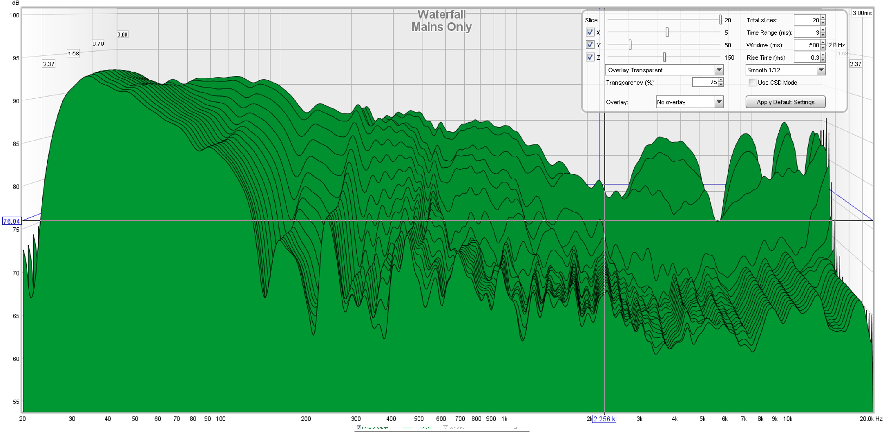
Wesayso this is the early waterfall graph of the outdoor MP version with 8 cycle FDW using the settings you have posted before. Can you tell me what you look for with this and why you find it useful?
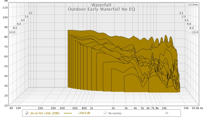
This is the most honest picture of what's really happening. Usually I limit the dB scale to be 25 to 30 dB below the average level (at about 1 to 2 KHz).
If you're looking for proof of comb filtering, this is it! The peaks and dips at the high end show the effects of comb filtering more than any other plot.
One of the reasons for me not to post the top end of a waterfall taken indoors. I do not want to start discussions about comb filtering. Change the distance or angle of the measurement and that pattern will change too. Which is why I believe it will be beneficial to average multiple measurements (representative of the listening area, possibly with some bias towards the sweet spot) and EQ/DRC based on that average.
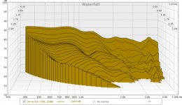
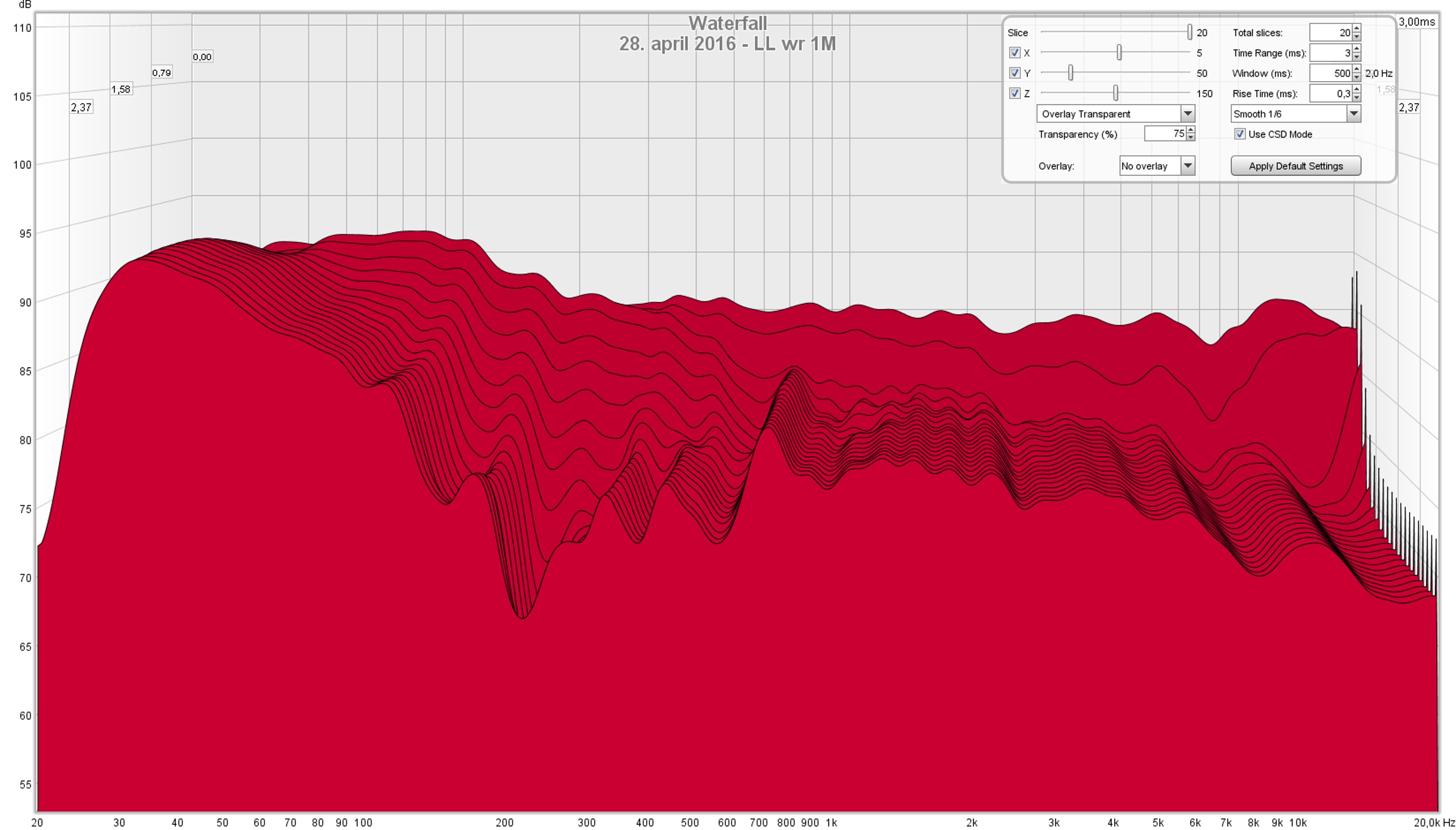
Here's an example (where I cut off the top end again 😉) up to 5 KHZ at my listening position after DRC has done it's thing and some (hand labor) post EQ:

BYRTT is right that the FDW will not influence what we see here. If we were to EQ that first ridge flat it would indeed show a different result in the following layers. Getting the results in this graph as clean as possible will also clean up the resulting impulse. The post EQ I talked about is always done while keeping an eye on both the early waterfall and the IR.
This will also teach you how the graphs each show the same thing with the only difference being it's presentation.
Aligning the peak energy with DRC will smooth out the graph some more, but not eliminate all peaks/dips we see here. I even tamper with what DRC does (with some EQ) based on what I see in the waterfall plots. EQ-ing the lower parts (below say 1-2 KHz), would require different settings for the waterfall.
Hi fluid as far as i know waterfall plot don't care and react to setting any FDW so must be based on raw IR but it has its own presenting possibility in setting smoothing numbers within 1/3-1/48.
I can see that the FDW doesn't have an effect on the waterfall graphs I probably shouldn't have added that into the graph title as it was confusing 😱
That makes sense, the outdoor measurement is more usable than I thought when a minimum phase version is generated. The phase was already pretty flat but it got rid of the bottom flips due to environmental noise. Should be a good base for starting EQ at least above 300Hz or so.Think some of wesayso's points is its easy to EQ first ridge smooth and flat to whatever target one prefer, problem is next ridges will start show resonances that get much worse than before EQ correction if EQ is based on any interference/reflections.
Do you mean gating the IR or something else?When EQ is based on windowed measurements and those windows settings are optimized for actual in situation not only into windowed curves things start look good but also raw windows start to look good including waterfall.
A single LM3886 per driver run on a low voltage would be interesting. Their distortion is higher at low powers though.An lm3886 giving max 240watt/25 < 10 watt needs very little cooling. So the advantage is that you spread the heat dissipating between 25 unit and need very low supply voltages
Maybe even the magnet can be the cooling element as the average watts/crest factor will be low/high with such bass eq as described here (26 db)
For me one of the main attractions of the full range array was that I could use a single stereo amp, my other systems are multiway active so I was looking for a less complicated amplifier arrangement 😀
I can understand that, it seems like the comb filter vigilante's are taking a break or aren't interested in this thread yet.One of the reasons for me not to post the top end of a waterfall taken indoors. I do not want to start discussions about comb filtering. Change the distance or angle of the measurement and that pattern will change too. Which is why I believe it will be beneficial to average multiple measurements (representative of the listening area, possibly with some bias towards the sweet spot) and EQ/DRC based on that average.
Multiple measurements and a Moving Mic measurement are on the list to do when I am at home.
Here's an example (where I cut off the top end again 😉) up to 5 KHZ at my listening position after DRC has done it's thing and some (hand labor) post EQ:
This is my outdoor measurement with no EQ and the same settings. Much cleaner looking than the other plot but DRC has done a good job in the first few milliseconds on your's.
Attachments
...Do you mean gating the IR or something else?
Right sorry my language its probably infected a bit from REW use (Window/Windowed/Apply Windows).
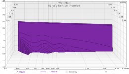
If you have time open below attached Rephase settings file which is a 17Hz-22kHz BW2 pass-band inclusive downward tilt, after generate import its IR into REW then center IR and offset spl at 1kHz to about 77dB line and hereafter generate waterfall with exactly same settings as plot wesayso shared, what he show there is acoustics example at listening position and simply fantastic, will guess it needs kind of gating 😀 and manipulating to get room and speakers cooperate as that.
Attachments
Yes his real world acoustics out at listening position is so close to the synthetic created perfect IR, no wonder i think remember whenever Jriver played tracks we always automatic sat smile and feel that included all locations being in the part of living room that is in fronts of arrays, entering sweet spot needed medicine to stop foot tapping.
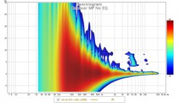
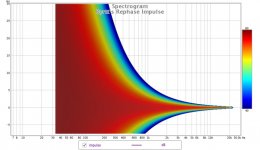
Pretty good spectrogram for a non smooth speaker response there, outdoor probably helps enormous for getting it so clean, good future signs and also that was before felt and sock wasn't it, plus your living room has a real carpet and that probably help a bit compared to a naked room.
It is better than I thought it would be, that measurement was without felt or sock. The room has carpet but it is made out of plastic, I know because it has melted elsewhere in the house 🙁Pretty good spectrogram for a non smooth speaker response there, outdoor probably helps enormous for getting it so clean, good future signs and also that was before felt and sock wasn't it, plus your living room has a real carpet and that probably help a bit compared to a naked room.
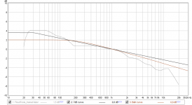
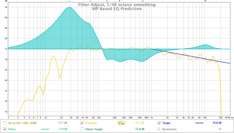
The new rough EQ is fairly close to your BK band limited response. Hard to say how much the low end will be boosted from room gain. I could use the Jeff Bagby spreadsheet but what height would I choose 😕
Attachments

Planning rough EQ overlay looks good fluid and ha ha you right there about height, one could make 25x different height spreadsheet and either average or multiple them on REW "ALL SPL" tab but then again you will probably end up calibrate on some real world data from speaker+room cooperation based on some advanced gating manipulating procedure.
For info downward curve into the pass band file is a more modern one having about 7dB downward slope from about 30Hz to 30kHz, if you like it use it for planning and target just change stop bands as needed. Have also B&K curve as Rephase settings file and find it attached below, low end plateau and downward slopes are bit different and as with above just change stop bands as needed. Theres is another modern one Floyd-Toole trained listener but i never got farther than traced it as rough frd-file seen below.
For info downward curve into the pass band file is a more modern one having about 7dB downward slope from about 30Hz to 30kHz, if you like it use it for planning and target just change stop bands as needed. Have also B&K curve as Rephase settings file and find it attached below, low end plateau and downward slopes are bit different and as with above just change stop bands as needed. Theres is another modern one Floyd-Toole trained listener but i never got farther than traced it as rough frd-file seen below.
Attachments
A single LM3886 per driver run on a low voltage would be interesting. Their distortion is higher at low powers though.
For me one of the main attractions of the full range array was that I could use a single stereo amp, my other systems are multiway active so I was looking for a less complicated amplifier arrangement 😀
I can understand that, it seems like the comb filter vigilante's are taking a break or aren't interested in this thread yet.The LM3886 has lowest distortion with simple PCB and low count components when driven up to 10 watts. Over 10 watt "fake", 5$, ebay ones that I was thinking of distorts more. I guess 0.01% is good enough.
And the main distorting problem with LM3886 is limited heat dissipation. So I would say this application is ideal.
Of course I would not change your very nice build. Just inspire others looking at quality/price
I think I "secretly" raised the comb filter/lobing issue by refering to the JBL article. I not sure it is such a problem in smaller rooms with lot of reflections.
My main consern with the design is the 26 dB 30Hz EQ rise. Maybe a test could be setting a 30 Hz sine on the speaker and measure the distortion on a 1k sine at -26 dB. I fear the drivers must work outside their best linear execution range
Last edited:
I think I "secretly" raised the comb filter/lobing issue by refering to the JBL article. I not sure it is such a problem in smaller rooms with lot of reflections.
If one considers the cross talk between two stereo speakers in a standard stereo setup to be "normal":
Left plus right speaker as measured at one ear (head is simulated by a dummy head) in a room performing at least equal to a real good studio environment.
Compared to a pure left ear/left speaker measurement in that same room:
It could change how you feel about comb filtering and it's related problems 😉.
Original links: http://www.diyaudio.com/forums/full-range/242171-making-two-towers-25-driver-full-range-line-array-233.html#post4745046 and http://www.diyaudio.com/forums/multi-way/277519-fixing-stereo-phantom-center-61.html#post4746283
This would only affect the phantom center and only be valid in a room without early reflections in the exact sweet spot. Still its grossly ignored by many.
My main consern with the design is the 26 dB 30Hz EQ rise. Maybe a test could be setting a 30 Hz sine on the speaker and measure the distortion on a 1k sine at -26 dB. I fear the drivers must work outside their best linear execution range
Don't look at it as a 26 dB EQ rise, it's more like a 16 dB EQ rise, covered or shared by 25 drivers. The ~200-500 Hz mid section will be far more efficient in an array and gets cut compared to ~1.5 KHz.
Each driver only sees about 11 watts(*) if we drive it to x-max excursion at 30 Hz. But that would almost never happen in real world use. I'm still running my arrays with an underperforming amp (about 100 Watt) and get plenty of low end, ask the people that heard it. I did not play with sine waves specifically but have shown plenty of distortion graphs that can rival systems with bigger drivers.
Even that 16 dB is up for debate depending on where one places the array in relation to boundaries. Sure the max SPL level is limited due to these drivers, not really a problem with music but one might run in to that problem with Home Theatre. But you'd have to play at really loud levels to run into that problem. My amp runs into problems long before the arrays do.
(*) I derived that 11 watts figure by running BYRTT's X-sim simulation of the series/parallel wired array to 240 watt. I have used WinISD Pro to find a theoretical level where x-max is reached. I did not look at thermal loads on the drivers.
Last edited:
Datasheet shows that THD+N goes down from lowest to highest power output but you are right that 0.01% at 10W is probably the sweet spot. Adding 25 together would mean that the distortion would be additive and be more like 0.25% for the combined amount.The LM3886 has lowest distortion with simple PCB and low count components when driven up to 10 watts. Over 10 watt "fake", 5$, ebay ones that I was thinking of distorts more. I guess 0.01% is good enough.
Either way they are very good amps and I have LM4780 amps in a multiway active system and they work nicely.
I think I "secretly" raised the comb filter/lobing issue by refering to the JBL article. I not sure it is such a problem in smaller rooms with lot of reflections.
I didn't read the JBL information as a short array like that does not work as well as a floor to ceiling design and needs the delay or amplitude shading to try and improve those problems. That's probably why I missed the comb filter reference 🙂
Much like wesayso I think the comb filter situation has been discussed to death. I will say this, you can see it in the raw measurements I posted. You can also see that it gets better with distance.
In practice playing pink noise and moving your head up and down the array you can hear it at less than a metre but it's not awful sounding. By the time you are more than a metre away you can sweep your head up and down as much as you like and it is barely audible.
Do the same thing on a multiway and it's no better.
My main consern with the design is the 26 dB 30Hz EQ rise. Maybe a test could be setting a 30 Hz sine on the speaker and measure the distortion on a 1k sine at -26 dB. I fear the drivers must work outside their best linear execution range
Hmm there is not 26dB of boost at 30 Hz, I have used 20dB of boost in a filter but there will be attenuation applied to that to avoid clipping so the value is only relative.
That is also to correct an outdoor measurement back to flat, when placed inside, the room gain should mean that can be reduced down but it will be placement dependant.
I don't understand the test you propose but there are already distortion measurements of arrays.
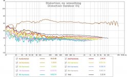
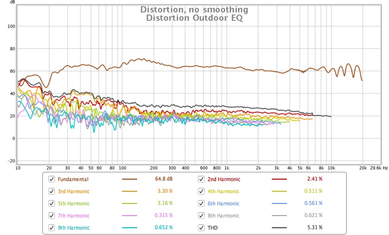
This is mine outdoors with the rough EQ applied. It definitely rises below 100Hz but there is absolutely no room support there and it is flat to 20Hz which is really an absolute worst case scenario that won't exist when they are used inside.
The level was a bit low and signal to noise would have suffered so some of the low distortion would be from environmental noise.
Wesayso posted this one on his thread, 87dB SPL at the low end and distortion is 40dB below the fundamental at 3m listening distance.

When I was testing with low tones I had to go down to 10Hz at a pretty high level from the amp to get the cones moving, at 30Hz I really struggled to get them to move, the EQ will change that a little but it is the very low frequencies that cause the real high excursions. Limiting output below 20Hz with a steep slope makes a real difference.
All designs have compromises you have to pick your poison.
EDIT: Wesayso beat me to it while I was typing 🙂
Attachments
http://www.diyaudio.com/forums/atta...-array-cnc-cabinet-mp-based-eq-prediction.jpg
* 26 dB rise at 30 Hz vs 250 Hz
* Not only the distortion gets added. Also the signal. So the relative distortion is the same.
* Thank you for posting honest distortion plots. 10% up to 50 Hz.
* The point of the 30Hz + 1 k test is that the 1k will get distorted when the 30 Hz "carrier" (rememper 10 tims the volts and that displacement is 4 times for every halfing of frequency) will bring the cone in and out of the linear region.
This is not a problem with every day listening levels.
But playing really loud (> 100 dB) distortion could be a problem.
I have put up a system myself with 6X12Inch long throw elements at 30 Hz and get 1 cm of execurtion when playing +110 dB. So the "worry" is based on experience not just theory.
(Then I have dameged my ears with the 6x12inch system, so distortion to tell you to turn it down, can be a good thing)
@Wesayso: I listen to comb filtering because of my floor and ceilling every day, so I don't worry to much🙂
Last edited:
* Thank you for posting honest distortion plots. 10% up to 50 Hz.
Where does this 10% number come from? Un EQ-ed line array as posted by fluid?
I couldn't think of playing 110 dB in my living room without everything starting to vibrate.
When I just finished the arrays and had only crude EQ I never noticed how loud I played it.
Only trying to start a conversation while playing them made me aware of the level. Ever since
that discovery my SPL meter is never far away. I limit my average levels to 85 to 90 dB max.
Yes I've listened louder, but the room starts to protest on bass heavy stuff.
Last edited:
http://www.diyaudio.com/forums/atta...e-array-cnc-cabinet-distortion-outdoor-eq.jpg
Shows distortion at -20dB (not so good) at 50Hz and -40dB (very good) at 125 Hz.
At 85 to 90dB I guess the distortion is no problem at all. And one could always have a sub lying around for parties. HP 100 Hz and there will be no line array distortion at all even at very, very high levels.
(My 6 sub room is made from 20cm loggs, but there is a lot of vibration, so, yes, its for Rock and Roll only. Then there are some subsonic filtered info on some recordings like planes or cars driving by, that makes the live/"beeing there" feeling very good. Actually you believe the car is driving by your own house)
Last edited:
- Home
- Loudspeakers
- Full Range
- Full Range TC9 Line Array CNC Cabinet