That would take even more wiring!
It certainly would, but what's a few more feet of wiring between drivers/friends? 😉
Wesayso,
How are your drivers currently wired and how many actual sealed chambers do you have? I seem to recall all your 25 drivers share one chamber but with smaller breather holes in between groups of them right? They sound so good now, I would hate to take them apart for some surgery that may or may not yield an audible improvement.
Regarding blowing up drivers. These are too small to hurt one another. 🙂
Yes, all chambers are connected but there's a lot of damping material in the path and the holes alternate vertically (not a straight shot).
I hate to take them apart too, but I'm pretty confident it won't hurt the performance. It just might make it even better 🙂.
I've had them apart a few times when I started out, no reason to chicken out now. It's why I build them like I did. Serviceable.
I've seen all the proof I need to give it a shot. I don't expect any array like these to cripple any drivers, the main difference will be right around the impedance peak. There's not enough power there to rip anything apart, though it might still bring benefits by evening out the load on the drivers. I expect the biggest difference to be at higher SPL. My impedance curve was pretty clean to start with. Though I'm too interested in what it can do not to try it.
It's the same with adding subs. Do I need them? Neh... but what if it does make a difference....
I'm as much into it for the learning curve as for the enjoyment. I just lack the time right now.
Based on the build photos, each speaker gets it's own resonant chamber, with acoustically damped walls based on the cutouts, and every chamber is connected by largish breathe holes as you said. EDIT: Wesayso beat me to my response! 😉Wesayso,
How are your drivers currently wired and how many actual sealed chambers do you have? I seem to recall all your 25 drivers share one chamber but with smaller breather holes in between groups of them right? They sound so good now, I would hate to take them apart for some surgery that may or may not yield an audible improvement.
Regarding blowing up drivers. These are too small to hurt one another. 🙂
= = = = = = = = =
That 6 woofer worst case scenario mentioned earlier was done with PRO audio woofers each capable of producing extreme SPLs, and the combined efforts of 5 such woofers would easily be capable to overpower and likely destroy a single driver if it got out of phase with the others, and this was exactly what happened. That was truly a worst case scenario, and I don't believe anyone's small driver line arrays would ever be destroyed in such a manner, even being stress tested with 10Hz sine waves.
However, a single driver misbehaving at any one point may create audible effects, and if the misbehaving drivers swapped positions with each other creating dynamic oscillations that may or may not be a harmonic or multiple of the frequency of driven sound, it would be undesirable. Full spectrum music is very different than pink noise or sine sweeps generally used with calibration equipment, and any misbehavior observed may be sporadic and difficult to control or repeat under testing. Simulations that use purely mathematical models will never accurately predict real world behavior.
If it did, then all models would perform exactly as expected, and for instance NASA would never have a failed mission or rocket launch, or worry about redundancy in all of it's designs, or make periodic trajectory corrections during a mission. I know speaker building is more of an art than rocket science, and I think anyone with a line array system they are happy with should follow the age old advice, "if it ain't broke, don't fix it."
The breakup modes of series versus parallel wiring arrangements may or may not be measurable, and it is possible the differences between driver arrangement A or arrangement B may be so small that it is difficult or impossible to measure or quantify, and surely not negatively affect the final product. For instance, if total distortion increased by .1% with series over parallel at some frequency range, yet the listener moving his or her head up or down an inch or so caused greater impact upon the sound in some other frequency range (definitely the case above ~5kHz or so), then the effects of different wiring methods might become completely negligible. Sometimes audiophiles may go through great expense or effort to get negligible increases in performance gains, so this may be the case with rewiring an existing line array.
Last edited:
Based on the build photos, each speaker gets it's own resonant chamber, with acoustically damped walls based on the cutouts, and every chamber is connected by largish breathe holes as you said. EDIT: Wesayso beat me to my response! 😉
= = = = = = = = =
That 6 woofer worst case scenario mentioned earlier was done with PRO audio woofers each capable of producing extreme SPLs, and the combined efforts of 5 such woofers would easily be capable to overpower and likely destroy a single driver if it got out of phase with the others, and this was exactly what happened. That was truly a worst case scenario, and I don't believe anyone's small driver line arrays would ever be destroyed in such a manner, even being stress tested with 10Hz sine waves.
However, a single driver misbehaving at any one point may create audible effects, and if the misbehaving drivers swapped positions with each other creating dynamic oscillations that may or may not be a harmonic or multiple of the frequency of driven sound, it would be undesirable. Full spectrum music is very different than pink noise or sine sweeps generally used with calibration equipment, and any misbehavior observed may be sporadic and difficult to control or repeat under testing. Simulations that use purely mathematical models will never accurately predict real world behavior.
If it did, then all models would perform exactly as expected, and for instance NASA would never have a failed mission or rocket launch, or worry about redundancy in all of it's designs, or make periodic trajectory corrections during a mission. I know speaker building is more of an art than rocket science, and I think anyone with a line array system they are happy with should follow the age old advice, "if it ain't broke, don't fix it."
The breakup modes of series versus parallel wiring arrangements may or may not be measurable, and it is possible the differences between driver arrangement A or arrangement B may be so small that it is difficult or impossible to measure or quantify, and surely not negatively affect the final product. For instance, if total distortion increased by .1% with series over parallel at some frequency range, yet the listener moving his or her head up or down an inch or so caused greater impact upon the sound in some other frequency range (definitely the case above ~5kHz or so), then the effects of different wiring methods might become completely negligible. Sometimes audiophiles may go through great expense or effort to get negligible increases in performance gains, so this may be the case with rewiring an existing line array.
If everyone would think like this, would we ever learn anything? 😉
By the way, this is measurable, like phase is measurable and even comb filtering in a stereo setup (or an array for that matter).
We can choose to ignore everything we want but that still doesn't mean it doesn't exist.
The difference between good and great usually consists of very small details. Personally I do not believe audio reproduction is an art form. See my signature. 😀
If it did, then all models would perform exactly as expected, and for instance NASA would never have a failed mission or rocket launch, or worry about redundancy in all of it's designs, or make periodic trajectory corrections during a mission. I know speaker building is more of an art than rocket science, and I think anyone with a line array system they are happy with should follow the age old advice, "if it ain't broke, don't fix it."
Rockets don't fail because of imperfect models. They fail because like any super complex system of systems, there are a lot of dependencies. The critical ones they try to go redundant. The best practice is to "Test what you fly and fly what you test". Thermal vacuum chamber tests, sine and random vibration test, acoustic test, RF test, fairing deploy test, entry and descent test, etc. and a paperwork trail a mile long to document it.
Still, things can go wrong and we end up with a bad day after 6 years worth of effort and $600M later. Cannot guarantee success with space missions.
Sorry for the OT but I will bring it back: having good models helps us to optimize things and to know what to look for when tweaking design and development. For example here, the Akabak model shows that there is an effect when series wired. It can be used one step further to see the sensitivity of certain TS parameters to see which one is really important to try to match to first order. I bet it is Vas and Bl or suspension stiffness and motor strength.
Last edited:
I will take any chance of an improvement anyway. I'm just "wired" that way I guess 😀.
Crazy! 😀
Crazy! 😀
Lock me up before it's too late!
An externally hosted image should be here but it was not working when we last tested it.
I am yet to see any evidence that series wiring is detrimental. Sure, it is different, but is it worse? Lots of questions to be answered. Contrary to the conclusions being drawn, from what I see it is not making any difference. The sims are great for this. And so far, they don't show any appreciable difference.
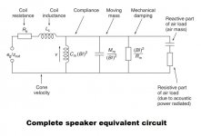
If you want to go "full monty" you would need to use the full electromechanical model of each driver. I sort of remember going over this in an acoustics class 10 (or was it 15...) years ago. Amazing how some things just pass through the grey matter 🙂
image taken from Speaker equivalent circuit / electrical model - Audio Judgement
image taken from Speaker equivalent circuit / electrical model - Audio Judgement
Attachments
I am yet to see any evidence that series wiring is detrimental. Sure, it is different, but is it worse? Lots of questions to be answered. Contrary to the conclusions being drawn, from what I see it is not making any difference. The sims are great for this. And so far, they don't show any appreciable difference.
My sims show an effect that cannot be called insignificant.
It requires that drivers have scatter in the TS parameters.
Here is cone displacemt for series:
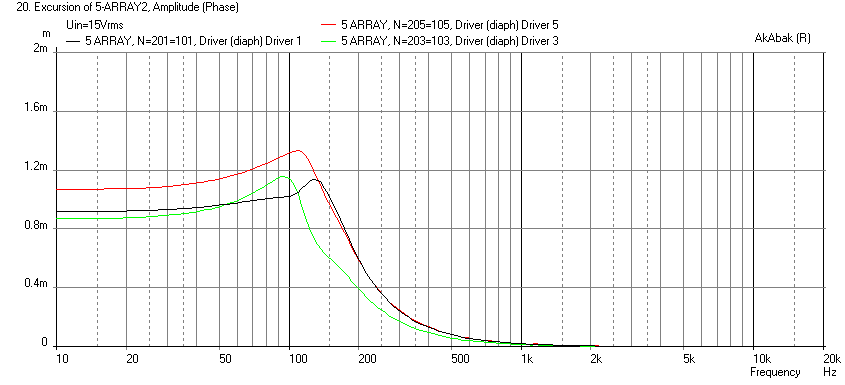
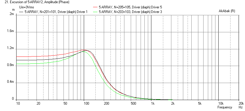
Here is parallel for same electrical input power:
If you want to go "full monty" you would need to use the full electromechanical model of each driver. I sort of remember going over this in an acoustics class 10 (or was it 15...) years ago. Amazing how some things just pass through the grey matter 🙂
image taken from Speaker equivalent circuit / electrical model - Audio Judgement
I am using the full electromechanical model of the driver. That's what TS (Thiele-Small) parameters are, and that's what's used in my Akabak model, which also accounts for the physical locations of the drivers within the chamber.
I think you are right that it is low frequency interference, the distortion is a lot higher in the very low frequencies. The cause is Road Trains and significant mine site activity. For those that don't know a Road Train is a 50 to 60m long truck, prime mover with up to four carriages, and my house is only 200m or so from the main highway.That's a spooky IR for outdoors any windmills with LF rumble in the neighborhood or any military radars sweeping nasty frq, looks your measurement gear is on track when doing a campare with measurment xrk971 did at 5º in his Dagger enclosure and shared with me about two years ago, thanks X.
As I said before I can't change the wiring, everything is sealed up and glued down between the chambers no way to add in extra parallel connections without destroying the cabinet.fluid, since your array uses 5 separate chambers here's a wiring idea you could try if you feel up to the task. Make the 5 series strings using one driver from each chamber. Then put those 5 strings in parallel. You would effectively be isolating the series wired drivers from each other and it would be as if each chamber has 5 drivers wired in parallel.
I think that is a very good point, at around 150Hz even running the amp full blast I can't even see the cones moving. With a 100Hz test tone I couldn't turn the amp all the way up as the pressure and feeling of the sound was nauseating. The EQ will change that somewhat but there is nowhere near as much boost at 150Hz as there is as 20Hz.The main difference will be around the array's impedance peak. 10 Hz tones won't be any different. I doubt it will be forceful enough to be able to destroy a driver as we still limit the power around that frequency area anyway.
That is the technical advantage but as yet I'm not convinced it is a big deal. X's sims showed no difference in frequency response, there was no phase but I don't imagine it to be much different. I still think distortion is where the difference will be and yours is pretty good in that regard 😉I'm mainly interested in the even load and movement on all drivers and certainly do see an advantage in the parallel wiring.
It is the frequency area where I had to work a little harder to get it where I wanted it (phase wise).
After all the work I put into my speakers I cannot neglect this new data. I'm always looking for ways to improve and the 100-200 Hz area is fun to have right both in phase and frequency. I don't know when, but I'm pretty sure I will alter my arrays after seeing these graphs.
Sounds like your curiosity has been tickled and we all know what happens then 🙂 One thing so consider is that your conjugate network will likely need some adjustment as the parallel versions seem to have a higher impedance peak with a higher Q. There is also the fact that you will have maybe 3 times as much wire in your cabinet. Given the fact you found differences in wiring you might want to consider that before taking your towers apart. The gauge of the wire will matter too or you might start loosing some high very high frequency output.Not looking forward to the surgery but I just have to do it. I cannot dismiss this, as I've said before, every detail counts if you want good results.
You've seen my distortion data, nothing to be afraid of if you don't alter the wiring scheme. I will take any chance of an improvement anyway. I'm just "wired" that way I guess 😀.
These things and the overall complexity of the wiring scheme is what put me off doing it that way in the first place.
The better balance of the drivers is clear from the simulations but the the effect that has on the output or sound of the speaker is not. It would be good if Owen could show some distortion data from his array to compare.Interesting comments from Owen and others, but there is still no theoretical reason for preferring one wiring approach over another.
My sims show an effect that cannot be called insignificant.
It requires that drivers have scatter in the TS parameters.
Here is cone displacemt for series:
Here is parallel for same electrical input power:
There is clearly closer agreement between the drivers around resonance in the parallel case. The thing that interests me is that below resonance the differences average out again where the gap between lowest and highest in the group is very similar. As this is the region where the EQ boost is at it's greatest that is where I would expect the outcome to be the most affected. As they are quite similar in this region it may be that there is very little actual difference in their measured performance.
I do hope I can show it one way or the other through actual measurements.
My sims show an effect that cannot be called insignificant.
It requires that drivers have scatter in the TS parameters.
Here is cone displacemt for series:
Here is parallel for same electrical input power:
There was no change in the frequency response---the primary determinant of what we hear. The small, minute changes in cone displacement near resonance could be attributed to individual differences in driver parameters. What is the mechanism by which these differences will present themselves in the magnitude response?
The cones are all displacing slightly different amounts in relation to their parameters in order to produce the same SPL (again, only near resonance). In the parallel scheme, the parameters are affected such that the drivers move differently to produce, again, and this is the most important part, the same SPL.
And why should we ignore the differences in cone displacement present in both parallel and series sims at other frequencies? Why doesn't that bother us?
Lets not put the cart before the horse; let's investigate and get evidence that proves there is a change in the magnitude response, maybe at high SPL or whatever. The evidence so far points towards no impact of wiring scheme.
Hi Guys,
I was on a trip for two days and lot has happened!!! This thread is hoppin' 😎
I first want to address a few questions from back in the thread:
No... we added a realistic amount of variance in the drivers. I don't think perfectly identical drivers would display this behaviour.
Matching drivers correctly would probably not be feasible even for a volume manufacture. Think about the logistics and inventory implications of this, especially with something like an array.
Simple... 5 parallel drivers share a common volume, and 5 of those parallel volumes are connected in series to get back to 8 ohms. That way, all drivers that share a volume are in parallel. The added benefit of this is that the series connected "segments" are already an average of 5 drivers, so there will be very little variation between the individual segments. This means that even if you have all 25 drivers sharing the same volume, there is still a significant advantage to wiring groups of 5 in parallel, and then wiring those in series.
No question about it... it was the series arrangement, and it happened more than once. Several prototypes were built, and the first time it happened it was assumed to be a driver issue. A company does not build custom 70 ohm drivers on a hunch 😉
Awesome... just awesome 🙂
Thank you for taking the time to run this! I know it's not a trivial effort.
Next up, I'd like to make a few clarifications:
1. I am not implying that you are going to damage drivers in your array if they are wired in series and share a common rear enclosure. As others have already said, the relatively low excursions, small Sd, large common volume, and lower playback levels at resonance all imply that there will not be driver damage. The example I gave involved six 12" drivers with well over 25mm of excursion all sharing a very small volume. This is obviously not the same as the arrays.
2. I am in no way implying that series wired drivers in a common volume in an array is guaranteed to sound bad. We don't have enough data to prove that one way or the other, but we will get there.
Based on the simulations from X, I'm not sure why anyone is trivializing this. Are you guys looking at the same graphs as I am? In the parallel example, excursion between drivers never deviates by more than 0.2mm. In the series example, excursion deviates by over 0.4mm which is not an insignificant amount when we're talking about an average of 0.9mm of total excursion!
xrk971,
Could you do me a huge favor and run the simulations again with two small (and presumably simple) changes?:
1. Change rear volume to 2L per driver. This is more representative of what myself and fluid are using.
2. Change input voltage to 9V for the parallel case and 45V for the series case. Running 3V in the parallel case works out to 28W for the entire array, and they require a whole lot more power than that. 9V works out to more like 250W which is what I needed to get down to 20-30Hz at decent output levels in a mid-sized room. It's still quite a bit less than the maximum power capacity of the array.
I think these two changes will help to better demonstrate the issue. All I need to see are the excursion graphs.
Finally, to ra7 and fluid:
I think you guys are confusing my general statement (which I think the data shows as being pretty accurate) with how that statement applies to your specific arrays. Please understand that I'm not trying to imply a series wired array is not going to work. For all we know, it could have little or no impact, and things like division of cabinet, damping, driver size and excursion levels at resonance might make all of this a non-issue for your specific applications. It seems as though you're missing the fundamental point though, which is that wiring drivers sharing a common volume in parallel results in lower deltas between the excursion of those drivers. This could become a significant issue, even with these little drivers, at higher output levels.
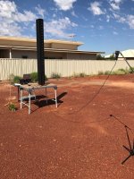
For my part, I will drag home my measurement equipment and measure my array outside this weekend and post up the results here. I will try and find a parking lot that is suitable and reasonably quiet. I can also take indoor measurements on Friday and provide those. I should be able to measure at 80dB, 90dB and 100dB. I'll see if I can measure at 110dB, but not sure I can make it that high.
I can measure distortion K2-K5 + THD and FR. I will also re-measure the impedance and see how things look. The arrays are almost 7 years old now, so it's probably time for a checkup 🙂
Regards,
Owen
I was on a trip for two days and lot has happened!!! This thread is hoppin' 😎
I first want to address a few questions from back in the thread:
Owen, did the sim at Blackberry assume identical drivers?
No... we added a realistic amount of variance in the drivers. I don't think perfectly identical drivers would display this behaviour.
A volume manufacturer could match, but that's not going to work for some who buys a few dozen from PE.
Matching drivers correctly would probably not be feasible even for a volume manufacture. Think about the logistics and inventory implications of this, especially with something like an array.
+1! But how do you connect 25 TC9 drivers in parallel? Owen worked at Paradigm and it sounds like they custom made the subwoofer voice coil impedance 35ohms, then put 6 in parallel?
Simple... 5 parallel drivers share a common volume, and 5 of those parallel volumes are connected in series to get back to 8 ohms. That way, all drivers that share a volume are in parallel. The added benefit of this is that the series connected "segments" are already an average of 5 drivers, so there will be very little variation between the individual segments. This means that even if you have all 25 drivers sharing the same volume, there is still a significant advantage to wiring groups of 5 in parallel, and then wiring those in series.
Owen, were you able to prove beyond doubt that the driver blowing up was caused by the wiring scheme? Or was it just a hypothesis?
No question about it... it was the series arrangement, and it happened more than once. Several prototypes were built, and the first time it happened it was assumed to be a driver issue. A company does not build custom 70 ohm drivers on a hunch 😉
I made a model of a 5 driver array with TC9FD's packed as close together as possible vertically.
Awesome... just awesome 🙂
Thank you for taking the time to run this! I know it's not a trivial effort.
Next up, I'd like to make a few clarifications:
1. I am not implying that you are going to damage drivers in your array if they are wired in series and share a common rear enclosure. As others have already said, the relatively low excursions, small Sd, large common volume, and lower playback levels at resonance all imply that there will not be driver damage. The example I gave involved six 12" drivers with well over 25mm of excursion all sharing a very small volume. This is obviously not the same as the arrays.
2. I am in no way implying that series wired drivers in a common volume in an array is guaranteed to sound bad. We don't have enough data to prove that one way or the other, but we will get there.
Based on the simulations from X, I'm not sure why anyone is trivializing this. Are you guys looking at the same graphs as I am? In the parallel example, excursion between drivers never deviates by more than 0.2mm. In the series example, excursion deviates by over 0.4mm which is not an insignificant amount when we're talking about an average of 0.9mm of total excursion!
xrk971,
Could you do me a huge favor and run the simulations again with two small (and presumably simple) changes?:
1. Change rear volume to 2L per driver. This is more representative of what myself and fluid are using.
2. Change input voltage to 9V for the parallel case and 45V for the series case. Running 3V in the parallel case works out to 28W for the entire array, and they require a whole lot more power than that. 9V works out to more like 250W which is what I needed to get down to 20-30Hz at decent output levels in a mid-sized room. It's still quite a bit less than the maximum power capacity of the array.
I think these two changes will help to better demonstrate the issue. All I need to see are the excursion graphs.
Finally, to ra7 and fluid:
I think you guys are confusing my general statement (which I think the data shows as being pretty accurate) with how that statement applies to your specific arrays. Please understand that I'm not trying to imply a series wired array is not going to work. For all we know, it could have little or no impact, and things like division of cabinet, damping, driver size and excursion levels at resonance might make all of this a non-issue for your specific applications. It seems as though you're missing the fundamental point though, which is that wiring drivers sharing a common volume in parallel results in lower deltas between the excursion of those drivers. This could become a significant issue, even with these little drivers, at higher output levels.
For my part, I will drag home my measurement equipment and measure my array outside this weekend and post up the results here. I will try and find a parking lot that is suitable and reasonably quiet. I can also take indoor measurements on Friday and provide those. I should be able to measure at 80dB, 90dB and 100dB. I'll see if I can measure at 110dB, but not sure I can make it that high.
I can measure distortion K2-K5 + THD and FR. I will also re-measure the impedance and see how things look. The arrays are almost 7 years old now, so it's probably time for a checkup 🙂
Regards,
Owen
The current between all series drivers is the same. The current between all parallel drivers is unique, so common sense implies there would be less variation between the series array, but the raw numbers prove otherwise.
With the six woofers, eliminate one driver and it gets shredded, regardless of series or parallel. I am surprised your company created a custom driver with high impedance instead of using an off-the-shelf driver and redesigning the amp, enclosure, or array. Partitioning the enclosure internally and sticking with a standard driver would likely have be cheaper than creating a custom driver.
With the six woofers, eliminate one driver and it gets shredded, regardless of series or parallel. I am surprised your company created a custom driver with high impedance instead of using an off-the-shelf driver and redesigning the amp, enclosure, or array. Partitioning the enclosure internally and sticking with a standard driver would likely have be cheaper than creating a custom driver.
Glad to see you made it back Owen. I don't understand how you think I have missed the point. This thread is primarily about the array I have built and I raised the issue based on my first impedance measurement that is a bit wonky.Finally, to ra7 and fluid:
I think you guys are confusing my general statement (which I think the data shows as being pretty accurate) with how that statement applies to your specific arrays. Please understand that I'm not trying to imply a series wired array is not going to work. For all we know, it could have little or no impact, and things like division of cabinet, damping, driver size and excursion levels at resonance might make all of this a non-issue for your specific applications. It seems as though you're missing the fundamental point though, which is that wiring drivers sharing a common volume in parallel results in lower deltas between the excursion of those drivers. This could become a significant issue, even with these little drivers, at higher output levels.
I'm not going to go back through the thread and quote myself or you but there has been a swing from don't worry about it to it will destroy the drivers and anywhere in between. As I cannot rewire my array to match your arrangement I would prefer the outcome to be that it makes no difference but am not closed to the possibility that there could be a worthwhile difference, it is then just something that I won't be able to benefit from.
What do you think will be the difference?
I totally understand and can see in the simulations that the parallel arrangement does a better job of driving everything more equally particularly around resonance. The sim from xrk is helpful as was the one from Byrtt but they do not take into account all the variables and show a trend on a graph not an actual audible or measurable difference in the standard set of speaker measurements. I hope that between you and I we can take enough measurements to show the difference and then we can discuss those.
I hope you can understand that I am not going to throw my speaker in the trash based on a simulation (of something different than the array I built too) 😉
This will be really helpful and I am grateful that you are willing to do that.For my part, I will drag home my measurement equipment and measure my array outside this weekend and post up the results here. I will try and find a parking lot that is suitable and reasonably quiet. I can also take indoor measurements on Friday and provide those. I should be able to measure at 80dB, 90dB and 100dB. I'll see if I can measure at 110dB, but not sure I can make it that high.
I can measure distortion K2-K5 + THD and FR. I will also re-measure the impedance and see how things look. The arrays are almost 7 years old now, so it's probably time for a checkup 🙂
I have taken some outdoor measurements today that I will post up plots of soon.
Here's the proof it happened 🙂
Attachments
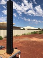
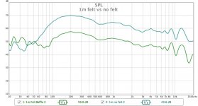
1 metre measurements
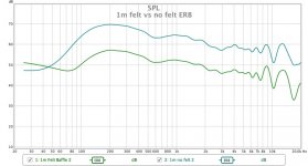
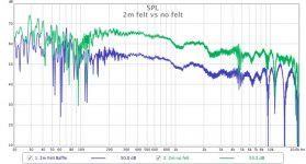
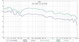
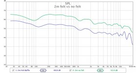
I have taken measurements of the speakers at 1m, 2m and 3m distance, with the felt in place and the speaker without. The speaker without felt has the drivers sorted and matched by the impedance peak.
I have measured without EQ and with the rough EQ. I didn't really get the level up enough for most of the measurements and the response below 100Hz is not to be trusted as it will no doubt be corrupted by noise.
The graphs are un-smoothed, 1/6 octave smoothed and ERB smoothed.
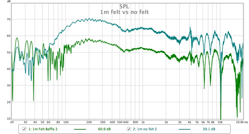

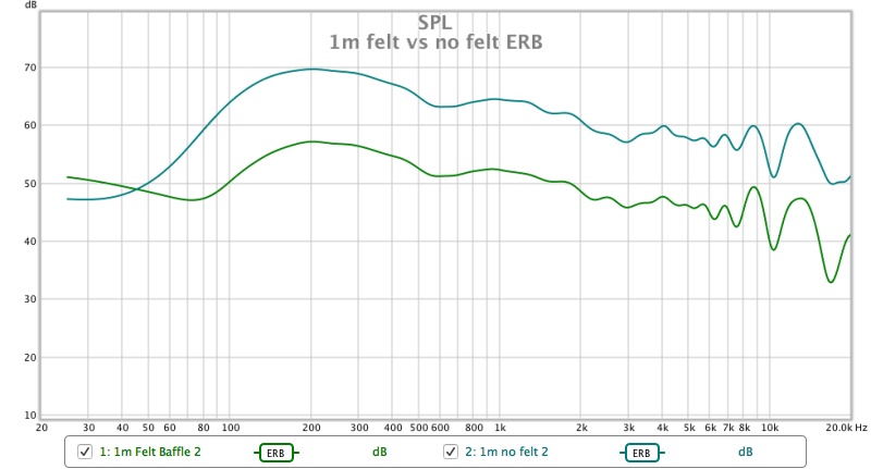
Up close the felt does do something to flatten the midrange a little
I have taken measurements of the speakers at 1m, 2m and 3m distance, with the felt in place and the speaker without. The speaker without felt has the drivers sorted and matched by the impedance peak.
I have measured without EQ and with the rough EQ. I didn't really get the level up enough for most of the measurements and the response below 100Hz is not to be trusted as it will no doubt be corrupted by noise.
The graphs are un-smoothed, 1/6 octave smoothed and ERB smoothed.
Up close the felt does do something to flatten the midrange a little
Attachments

Judging by the grass, you live in an arid region. Sun came out today in LA (the state) as it rained almost nonstop the past three days and will rain again this weekend.
That second photo of the speaker tower against the sky is gorgeous and I could imagine cropping it to show a skyscraper towering into the sky.
And that felt really damps the midbass hump by about 10dB. You wouldn't think surface treatment to the baffle would have such a dramatic effect but a lot flatter overall. Where are your 2m and 3m measurements?
Last edited:
- Home
- Loudspeakers
- Full Range
- Full Range TC9 Line Array CNC Cabinet