Hi everyone,
First of all, I would like to thank the community for the great dissemination done in this forum, I appreciate it for helping me with many aspects involved in the audio processing.
Basically, I am writing to you about my last project regarding the active sub filter. Many years ago, when I was 20 yo, I built a TL subwoofer with the same enclosure and size of the AWCS (BOSE) and the corresponding active filter. Besides my knowledge at that time, I had managed to solve many issues involved in its design (L and R separation,L and R mixing, grounding loops, noise etc). Lately, I decided to improve the mid and high range, thus I need to recalibrate the bass level, consequently the past design is no longer suitable for me, because it was not adjustable.
Looking for this forum I came across in two different posts, as usual I take the interesting part of several schematics, then I modify them in order to fit my needs. In these case, to build an active sub crossover, I decided to consider these two schematics:
https://www.diyaudio.com/community/threads/my-balanced-line-receiver.398440/
https://www.diyaudio.com/community/threads/active-subwoofer-filter.299230/
my design is made up of the following stages:
After this preamble, I would like to know if this design is fine or it requires some mods, in few words, what do you think about it? Did I do some mistakes?…
At the end of the project I am going to share the final schematic, gerber etc. using SMD components on EasyEDA platform.
Thanks in advance.
Roberto
First of all, I would like to thank the community for the great dissemination done in this forum, I appreciate it for helping me with many aspects involved in the audio processing.
Basically, I am writing to you about my last project regarding the active sub filter. Many years ago, when I was 20 yo, I built a TL subwoofer with the same enclosure and size of the AWCS (BOSE) and the corresponding active filter. Besides my knowledge at that time, I had managed to solve many issues involved in its design (L and R separation,L and R mixing, grounding loops, noise etc). Lately, I decided to improve the mid and high range, thus I need to recalibrate the bass level, consequently the past design is no longer suitable for me, because it was not adjustable.
Looking for this forum I came across in two different posts, as usual I take the interesting part of several schematics, then I modify them in order to fit my needs. In these case, to build an active sub crossover, I decided to consider these two schematics:
https://www.diyaudio.com/community/threads/my-balanced-line-receiver.398440/
https://www.diyaudio.com/community/threads/active-subwoofer-filter.299230/
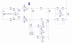
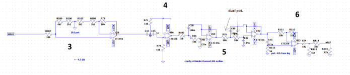
my design is made up of the following stages:
- two balanced line receivers to get the max CMRR and to separate the ground between the external DAC and the main amplifier;
- an arithmetic mixed which does the averaging of the both signals (no amplification is needed at this step;
- signal amplification/attenuation + - 4.5 dB
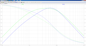
- second order high pass filter (15 Hz cut-off freq.)
- two second order bessel low pass filters in series (the last one can have an adjustable cut-off, both have a cut off freq. of 80 Hz, (the TL sub resonates a lot around 100 Hz thus I need to get a plain response, also a 4th order is the minimum).
- Lastly, a phase control in order to accord it with the TL midwoofer I’m designing now, the bessel type of the LP-filter should in theory help to have a plane and effective control of the phase.
After this preamble, I would like to know if this design is fine or it requires some mods, in few words, what do you think about it? Did I do some mistakes?…
At the end of the project I am going to share the final schematic, gerber etc. using SMD components on EasyEDA platform.
Thanks in advance.
Roberto