pretty, but wrong!
In that post you referred to, I attached a detailed drawing with numbered lines. You may need to print out that drawing so you can follow along in the text, where I refer to the lines by their numbers.
My method depends on a few simple rules:
1. A ray that passes through the center of a lens is not refracted, so it does not change direction.
2. Rays that are parallel on one side of a lens will be focussed to meet at the focal plane on the other side of the lens.
3. A ray refraction that occurs in one direction, will occur along exactly the same lines in the other direction.
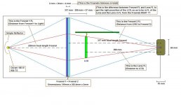
I construct a ray parallel to the outer edge ray (the one from the top edge of the fresnel to the top edge of the lens), but passing through the center of the lens and out the other side. Then I draw another ray from the top edge of the lens to the point the parallel ray intersects the focal plane of the lens. That shows you the refraction that will occur at the top edge of the lens. If you put the lamp arc at the point the refracted ray crosses the horizontal axis, then light would follow that ray to the top edge of the lens, get refracted, and then hit the top edge of the fresnel. This all works because of rule #3: Everything is reversible.
In that post you referred to, I attached a detailed drawing with numbered lines. You may need to print out that drawing so you can follow along in the text, where I refer to the lines by their numbers.
My method depends on a few simple rules:
1. A ray that passes through the center of a lens is not refracted, so it does not change direction.
2. Rays that are parallel on one side of a lens will be focussed to meet at the focal plane on the other side of the lens.
3. A ray refraction that occurs in one direction, will occur along exactly the same lines in the other direction.
I construct a ray parallel to the outer edge ray (the one from the top edge of the fresnel to the top edge of the lens), but passing through the center of the lens and out the other side. Then I draw another ray from the top edge of the lens to the point the parallel ray intersects the focal plane of the lens. That shows you the refraction that will occur at the top edge of the lens. If you put the lamp arc at the point the refracted ray crosses the horizontal axis, then light would follow that ray to the top edge of the lens, get refracted, and then hit the top edge of the fresnel. This all works because of rule #3: Everything is reversible.
Thanks guy, i get it now...heres an updated drawing...works a whole lot better than just redrawing it each time, just plug in the numbers and it does it all for you.
An externally hosted image should be here but it was not working when we last tested it.
pretty, and right!
Very nice. It would be even nicer if it printed the distance from the lamp arc position to the condensor lens, and the condensor lens to the fresnel. But those will really just be estimates: This model assumes that the condensor is a thin lens, but condensors are anything but thin!
You have to measure distances from the principal planes of the lens. For a thick plano-convex, like most condensor lenses, Principal Plane 1 is somewhere in the middle of the lens and Principal Plane 2 is at the farthest right surface of the lens. (I think PP1 intersects the top and bottom edges of the right surface, but that would be affected by the lens mounting.) Any measurement to the left of the lens is relative to PP1. Any measurement to the right of the lens is relative to PP2.
BTW: Please forget what I said about critical angle a few posts back. I ran an experiment with a laser and a good PCX condensor lens: The lens does refract light at much steeper angles than I thought. I read some more and realized that critical angle reflection only occurs when light passes from a higher index of refraction material into a lower (ie. glass into air). It does not really have anything to do with the reflectivity of the surface. The refraction just gets so extreme that the resulting ray never leaves the glass. So I have revised my ideas about how steep an angle you can use at the edge of a condensor lens.
BTW: Please forget what I said about critical angle a few posts back. I ran an experiment with a laser and a good PCX condensor lens: The lens does refract light at much steeper angles than I thought. I read some more and realized that critical angle reflection only occurs when light passes from a higher index of refraction material into a lower (ie. glass into air). It does not really have anything to do with the reflectivity of the surface. The refraction just gets so extreme that the resulting ray never leaves the glass. So I have revised my ideas about how steep an angle you can use at the edge of a condensor lens.
I made the exact same mistake a few months back lol.
I’ve got a concern with your graphical method of finding the ideal pre-condenser position. It appears that theory doesn’t match practice in this case. For a 17” LCD and 220mm fresnel, using your method, a 200mmFL 100mm dia lens needs to be placed at about 169mm from the fresnel and the lamp at about 40mm from the pre-condenser. In practice the lamp has to be moved much closer to the pre-condenser. In my testing it needs to be about 20mm from the principal plane to get the correct divergence. I think our friend spherical aberration is at work here again. I set up a test in Raytrace and it to seems to agree with your graphical method, so there is something that these methods are not taking into consideration. Perhaps if the angles of incidence were not as large, this method might get a closer practical estimate but at the moment I’m not too confident about it.
DJ
I think you are right
I have always said the graphical method is a way to find a starting point, not an optimal solution. It is essential to experiment with this stuff, to try different adjustments. The graphical method assumes a perfect lens with no thickness: No such lens exists! Just the location of the principal planes throws the measurements off quite a bit.
And I agree that spherical aberration would make the cone of light narrower than expected. Switching to an off-the-shelf aspherical condensor would not help at all, because they are designed to compensate for the aberration when the lamp is at the focal point of the lens (giving more parallel rays out the other side). If you move the lamp, the compensation doesn't work, and actually makes it worse.
There is only one substitute for experimenting yourself, and that is to use exactly the setup somebody else has found to work. It may not be the optimal solution, but at least it is A solution. For example, buying DIYBuilderGroup's condensor for a 15" LCD & 220 mm fl fresnel may not be theoretically optimal, but it may be close to the best practical solution for that projector design. I don't know...
Anybody else have any theory versus real condensor behavior results to report?
He Skiguy, what'd you decide??
Hey Skiguy, just wondreing what you decided to do. I'm aiming for a similar setup, 7" lilliput, 250w MH and 240mm objective lens. Did you order the 330/220 fresnel set? What did you decide on a condenser and reflector? Did you get the distances for those components?
Hey Skiguy, just wondreing what you decided to do. I'm aiming for a similar setup, 7" lilliput, 250w MH and 240mm objective lens. Did you order the 330/220 fresnel set? What did you decide on a condenser and reflector? Did you get the distances for those components?
Hey, check out my thread in diy projectors.
http://www.diyaudio.com/forums/showthread.php?s=&threadid=52532
http://www.diyaudio.com/forums/showthread.php?s=&threadid=52532
Help needed... similar setup.
Hi, I'm planning on using a 290 mm Lens, can you please help me on choosing and placing the Fressnels setup ?
I think from what I read, a 220 mm and 330 mm fresnels will work fine, no ? But what's the place for them ???
Light - 220 mm Fressnel - LCD - 330 mm Fressnel - 290 mm Lens ?
My fresnels are gone be 15" size and my LCD only 5" or 7".... I'd prefer not cutting the fressnel, but If have no option.... suggestions ?
Thanks
not enough info
Do you really need to use a split design? (field fresnel after LCD) This will let you do keystone correction, but you get a better screen image without splitting.
You need to pick a throw distance to be able to calculate the fresnel positions. Maybe that is limited by the size of your room, or where you want to place the projector? If you want to base that on the image size, then you need to pick an LCD size.
In general though, the 220/330 combination will be very good for a 290 mm projection lens.
What about this configuration ?
Guy or any experinced one... what do you think of my desing ? The only think I have doubts is this:
I'd like to preserve my fresnels untouched, so if in the future I'd like to use a bigger LCD, I will be able too... so, my doubts:
1) My fresnels are 319x254 mm and my LCD is only 125 mm diagonal (5" PsOne).... then... Where should I put the LCD ? In the middle ? It's the same anywhere ?
2) If I put the LCD on the top or in the middle, should I modify any of the distances to LENS or fressnel ?
3) Again, if I put the LCD on the TOP for example, is it better to move the lens to the top on the same line ?
I have this skretch to check.....
THANKS TO EVERYONE.
Attachments
hi
you don´t have to place the projection lens at the focal distance from the lcd, it doesn´t work this way.
The distance from the lcd to the projection lens depends only on the throw, (throw=distance from lens to wall)
by the way, let me tell you that i find your setup something strange. You have 29 cm focal lens, and 5" lcd. Lets say you want 80" image on the wall, then you need 5 meters of throw. Do you know that?
Yes.... I know....
I'm thinkin on 3 mts to get a 50" projection... at least for the begining... then I'll get 4 mts in the future. I think it's ok for me right now, but the problem is, what distances from Fresnes 2, LCD and Lens....... with my parts now, and a 3 mts throw, and 4 mts in the future.
Suggestions ?
I'm thinkin on 3 mts to get a 50" projection... at least for the begining... then I'll get 4 mts in the future. I think it's ok for me right now, but the problem is, what distances from Fresnes 2, LCD and Lens....... with my parts now, and a 3 mts throw, and 4 mts in the future.
Suggestions ?
Do this work ???
By the way, I cannot place the copy lens nearer than 290 mm to the LCD, no ? Let's say, if I can put it at 250 mm, I can get a bigger image, imagine my fresnels are BIG, very big in comparison with the LCD.... so if I place the LCD around 70 mm from fresnel 2, and 250 mm to the LEns.... I'll get bigger image, but I think that woun't work, no ?
THanks !
you can´t place the projection lens closer than the focal lengh of the lens. Mean if it is 29cm focal, if you project to the infinity then you need to place at 29, i think you haven´t such a big room.
1/29=1/D + 1/T
D=lens-lcd dist T=trhow
Do some math 😀
1/29=1/D + 1/T
D=lens-lcd dist T=trhow
Do some math 😀
Yes... I was on that...
Yes, I was working on that... **** ! Then, the only thing I can DO is 4 mts... because with my Fresnel at 317 mm, and a 290 mm Lens... with 4 mts throw I can put the LCD at 312 mm from Lens... it's very near to the Fresnel, but it's my only chance.... at 3 mts I go to 321 mm (And that's not good....) !!!! I'm busted !!!!!!!! $&$"&#"%$%/$%&....
Then I must be thinking on splitted fressnel, no ? Or I must die on 4 mts.... no ?
Thanks.
No, don't worry!
Put both fresnels about 20 mm before the LCD. (Any closer and you will see fresnel rings in your screen image.
The you can adjust the distance from the lamp arc to the condensor fresnel (just a few millimeters) to get the arc image into the projection lens.
If you change the throw distance later, you might be able to get a brighter image by adjusting the lamp arc to condensor fresnel distance again.
Don't forget to put a mask around your small LCD so there is no light going directly from the fresnels to the projection lens.
Mopheus questions 1, 2, 3: Your drawing is correct. Put the LCD in the middle, it is NOT the same anywhere. The distances will be correct if you do that.
137mm fl lens, psone lcd..shorter fresnel FL?
well this seems like a likely thread for this question... I have a psone/verge lcd (5 inches) and have a 137 mm fl triplet(copy lens) ... now I found a thread with those qualifications and the builder used 4 fresnels before ther lcd...the odd thing(to me) was that he p[laced the fresnels groove to groove in 2 sets...(ie 2 unsplit pairs) ... wouldn't it be groove to flat(2 each eg |- |- -| -|... the "-" being the groove side, or I suppose just one collimating fresnell) I suppose total light path is all that matters but ? also, I'm guessing that with a 137 mm FL triplet I will need to put 2 fresnels together to shorten the focal length? so 2 330mm lenses togethr would be 150mm FL? any optical insights here? and according to above formula, I'll get a 60 inch diagonal about 5 foot throw? (which would be good)
well this seems like a likely thread for this question... I have a psone/verge lcd (5 inches) and have a 137 mm fl triplet(copy lens) ... now I found a thread with those qualifications and the builder used 4 fresnels before ther lcd...the odd thing(to me) was that he p[laced the fresnels groove to groove in 2 sets...(ie 2 unsplit pairs) ... wouldn't it be groove to flat(2 each eg |- |- -| -|... the "-" being the groove side, or I suppose just one collimating fresnell) I suppose total light path is all that matters but ? also, I'm guessing that with a 137 mm FL triplet I will need to put 2 fresnels together to shorten the focal length? so 2 330mm lenses togethr would be 150mm FL? any optical insights here? and according to above formula, I'll get a 60 inch diagonal about 5 foot throw? (which would be good)
not as bad as you think
I don't think fresnels work very well if you try to go far from parallel light on the grooved side and lamp or focal point at the focal length on the smooth side. But you don't really need to do that:
You have a 137 mm fl lens with a 5 foot throw, so your LCD to lens distance will be about 150 mm. You can find 200 mm fl fresnels for sale (such as 3dlens.com A260), so I would suggest you get two of those. Put them (grooves touching) about 50 mm before the LCD, with the lamp arc about 200 mm from the fresnels. That should focus the light into the projector lens.
You will need to make them about 50% larger than the LCD, so the converging cone of light still fills the LCD from 50 mm away. But that should be no problem, since they come a lot bigger than that.
If you get that all working, you could get a brighter image by adding a pre-condensor lens near the lamp.
BTW: a pair of 330 mm fl fresnels together would have a fl of 165 mm.
thanks guy, I will try that(assuming I can wait fior the delivery from 3dlens...... so they could be 50mm behind the lcd? wasn't sure how far back to set them.... most numbers I've heard are about 20mm and because of the "overhang" of the circuit board above the ps1/verge lcd 20mm is a little too close, I would have had to cut the fresnels down really close....thanks for your help....
fresnel to LCD distance
In an unsplit design, you can set the fresnels back as far as needed. But then you do have to make them wide enough to still light the whole LCD. If your fresnels are cut to the exact LCD size, then they need to go close. Any closer than 20 mm will show fresnel rings in the image.
In a split design, the light goes pretty much in parallel through the LCD. So the condensor fresnel can be 20 mm up to maybe 200 mm? before the LCD. And the fresnels can be cut to about the LCD size, even if it has a lot of space. The distance between the LCD and the field fresnel is more critical. Closer than 20 mm will show rings in the image. Too far away will distort the image.
- Status
- Not open for further replies.
- Home
- General Interest
- Everything Else
- The Moving Image
- Optics
- Fujion Copy lens 240mm, best fresnel for it?