Hey guys, I have 6 transformers for sale. They were removed from current professional amplifiers. They give a +/- 96Vdc output unloaded. The rectifier PCB can be configured for 120 or 220 operation but the transformer is rated for 120V only. The rectifier PCB includes 2 separate bridges, fuses, NTC, and a fan speed circuit. How about $75 shipped.
If you have any questions please don't hesitate to contact me. Thanks!
If you have any questions please don't hesitate to contact me. Thanks!
Attachments
Howdy Evan Shultz,
Two kinda important issues.......
How many watts?
And, don't see any center tap ground wire in the pic.
Regards,
Elvin
Two kinda important issues.......
How many watts?
And, don't see any center tap ground wire in the pic.
Regards,
Elvin
Yep, you are correct. Sorry about that. Thanks for asking.
They are from RMX850 amps - 830W into 4ohm.
Because those amps use separate secondaries for each channel there are separate rails and the ground is derived from the center of the caps.
They are from RMX850 amps - 830W into 4ohm.
Because those amps use separate secondaries for each channel there are separate rails and the ground is derived from the center of the caps.
Member
Joined 2002
how many va is the tranny ?
and thats 96V x 2 right so.. through caps you might get about 100V rails ?
and thats 96V x 2 right so.. through caps you might get about 100V rails ?
Sorry, let me try this again:
There are dual secondaries. Each one is 96Vdc top to bottom unloaded. You can configure the amp to +/- 96V or dual +/- 48V. I don't know the VA rating.
And yes, with capacitors the unloaded voltage will increase.
There are dual secondaries. Each one is 96Vdc top to bottom unloaded. You can configure the amp to +/- 96V or dual +/- 48V. I don't know the VA rating.
And yes, with capacitors the unloaded voltage will increase.
Howdy Evan,
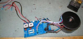
I appears that the secondary has four wires:
green, pink, blue and purple.
Now if this is any kind of "standard" winding, some combination of two of the four wires will be the proper "center" ground point and the other two wires will be proper AC out to the bridge rectifiers. The printing on top of the circuit board may give a clue, or look on the traces on the bottom for ideas. One can also trace this out with a meter if you know how.
Now, in addition there are two fuses on the board. Their value (250V 12A fer instance) would tell us some reasonable approximation of what they are intended to protect. Most of us can do the math to figure Watts. If it's pretty heavy, like 20-30 pounds, then it could be 10A or more at +/-96V. Very nice for a Leach SuperAmp application making pretty near 300 W/ channel on that beast.
But then a prudent builder would want 125V caps. Do you also have the capacitors? That would be most helpful if they were say 10,000uF at 125V. This kind of info would certainly increase my personal interest in a couple of your "cast offs".
Regards,
Elvin
The secondaries are totally separate. The center tap is derived from the center of the capacitors. If you look at the schematic of an RMX850 you will see the completely separate secondaries for each channel and configuration of the amp dictate this type of power supply. The schematic also reveals 80V capacitors for each rail.
Each fuse is 250V 10A.
The dimensions are 3.25" tall and 4.75" diameter including the top plate.
3 have a bare metal top plate and the other 3 have black painted top plates.
Each fuse is 250V 10A.
The dimensions are 3.25" tall and 4.75" diameter including the top plate.
3 have a bare metal top plate and the other 3 have black painted top plates.
- Status
- Not open for further replies.