I have designed a small filter board for use in my Bass amp and to get the best prototype PCB board pricing i needed to have several made at a time if anyone would be interested in one at my cost.
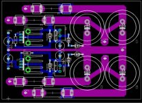
Each board is about 3x5" and contains 4x 15,000uf 80v 35x60mm filter caps set up to provide independant dual + and - outputs with fuses inline with each of the 4 outputs. the HV side is dual layer with duplicate top and bottom traces with single sided plated through hole traces for the regulator section.
PLUS a layout for the Pass Zen 3 +/- voltage regulator to power a lower voltage front end. The regulator is set up to use TO-220 type pass devices. I have not yet tested this layout, but i havecomplete faith in Mr.Pass's regulator designs, i mean come on who wouldnt right??
You could just use the PCB for the filter caps and fuses and not use the Low Voltage regulators, or??
Each board will come loaded with the filtar caps, fuse holders, and most of the regulator parts including the TO-220 Pass mosfets.
If you want the regulator section loaded up to Provide +/- 15vdc the same as what i am using, i will do that at no extra charge. otherwise i will load up the regulator sections and leave the Zeners and associated resistors off for you to DIY.
I am still calculation the final costs. but each board will be around $50.00 at quick glance of the parts cost's.
Again i am not doing this for profit, just trying to help offset my cost of having one of these made for myself!
and if you have a SWR SM-900 bass amp, this should be a drop in upgrade board for your amp!!!
Disclaimer, the regulator design here is the intellectual property of Nelson Pass.
Please email me at tetech2@doitnow.com for more info.
Zero Cool
Attachments
kilowattski said:Zero,
Why not put the rectifiers on the board? Why only 30,000uF per rail?
The board was designed for a specific application. as a drop in replacment board for my SWR bass amp. I needed to keep the board as close to the stock size as possible, plus with the free version of Eagle Cad i can only make the board so large(80x100mm) and i am at the limit now.
I was trying to get 6x caps on the board and just couldnt stuff it all in there. even still, the stock board uses 4x 6,800uf caps so 4x 15,000uf caps will be a large improvement.
and, the largest caps i could find that would fit in the space allowed were the 35x60mm 15kuf caps, stock is 30x50 and i can just squeeze the 15k's under the hood.
The SWR uses a bridge rectifier mounted directly to the chassis for a bit of heatsinking i would imagine.
Im no great PCB layout guy, but if there was enough demand i would be willing to resdesign the boards however you want.
Zc
I was just curious. I was not aware of your space restriction. Looking at your design, I think you did a good job.
Thanks, I spent a lot of time thinking through the design. I am still learning how to use the Eagle Cad software. its not the most intuitive thing to learn. You have to have a solid parts list with exact part sizes figured out. AND, then trying to figure out how to make a Gerber file and Drill list was a PITA!!! there seriosuly needs to be an easier way.
I have the basic hang of it now. i learn a bit more with each board i make. this is the most adventurous board yet so we will see how well it works out. I will post photos of a completed board here.
Zc
I have the basic hang of it now. i learn a bit more with each board i make. this is the most adventurous board yet so we will see how well it works out. I will post photos of a completed board here.
Zc
- Status
- Not open for further replies.