I have some of these units for sale. They are the classic yellow drivers that were used in the B&W 800 series for years up until the latest Silver "Continuum".
They are extremely sensitive (around 93dB/W) as a result of the lightweight Kevlar diaphragm and large vented Neo motor.
If you are designing a 3-way speaker and want a very low distortion unit these could be for you! Bandwidth 200Hz - 10kHz.
Let me know if you are interested
TC
They are extremely sensitive (around 93dB/W) as a result of the lightweight Kevlar diaphragm and large vented Neo motor.
If you are designing a 3-way speaker and want a very low distortion unit these could be for you! Bandwidth 200Hz - 10kHz.
Let me know if you are interested
TC
I just want to clear these out now please, I have 9 Mids left.
Highest bidder by Sunday gets them.
Thanks
Highest bidder by Sunday gets them.
Thanks
Really nice drivers for midwoof use- I'd use them with a midtweet and tweet (massively multiway a la nautilus).
Further to this - they are suitable from around 250Hz to 10kHz so perfect for a 3-way.
Quantity is likely to be less than 9 now as a few people have made enquiries..
Any further offers?
Quantity is likely to be less than 9 now as a few people have made enquiries..
Any further offers?
Okay so just in case anyone is interested I bought a pair of these and compared them to the ones that Zaph measured.
What interested me mostly about this model (apart from the low eBay price!) was that they were 'shielded' and came with a bucking magnet. Usually this increases the net sensitivity of a driver.
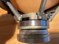
As anyone who's looked at my website has seen I turned the other FST pair into a co-axial driver. This isn't so easy with this version as anyone who removes the phase plug will be able to see. There's a threaded chunk of aluminium glued to the top of the pole piece for the phase plug to screw into, rather than the other one where the phase plug goes directly into the pole. This means there's no space within the voice coil former for a tweeter to sit in, this space is taken up by the threaded chunk of aluminium.
I'm tempted to say that you can probably remove this threaded piece of aluminium with some creative thinking. You can see that it's glued to the pole, rather than an extension of it, because the copper cap is visible, as a discrete layer, between the pole and the threaded section. It just depends on what adhesive they used to glue them together.
On to the measured performance. I'm not going to post any graphs because these were quick and dirty but the upshot is this. Harmonic distortion is on a par with the one Zaph measured. These have 2-3dB more sensitivity and a lower Qts as a result of the additional motor strength. All in all a slight improvement if you ask me.
What interested me mostly about this model (apart from the low eBay price!) was that they were 'shielded' and came with a bucking magnet. Usually this increases the net sensitivity of a driver.
As anyone who's looked at my website has seen I turned the other FST pair into a co-axial driver. This isn't so easy with this version as anyone who removes the phase plug will be able to see. There's a threaded chunk of aluminium glued to the top of the pole piece for the phase plug to screw into, rather than the other one where the phase plug goes directly into the pole. This means there's no space within the voice coil former for a tweeter to sit in, this space is taken up by the threaded chunk of aluminium.
I'm tempted to say that you can probably remove this threaded piece of aluminium with some creative thinking. You can see that it's glued to the pole, rather than an extension of it, because the copper cap is visible, as a discrete layer, between the pole and the threaded section. It just depends on what adhesive they used to glue them together.
On to the measured performance. I'm not going to post any graphs because these were quick and dirty but the upshot is this. Harmonic distortion is on a par with the one Zaph measured. These have 2-3dB more sensitivity and a lower Qts as a result of the additional motor strength. All in all a slight improvement if you ask me.
Good to know it measures comparably. I have listened to mine free air but not measured. Sound reminds me of some high efficiency PHLs with flat surrounds or even the Manger driver.
Just for reference, here's your own thread at htguide, Zaph's blog and another discussion of Zaph's measurements in German (but autotranslate is pretty good these days - if it fails, use deepl).
B&W FST mid
Zaph|Audio
Zaph hat B&W Mitteltöner gemessen
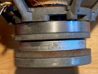
I don't think it is a bucking magnet. The top and bottom plates are beautifully turned, and one wouldn't even need to use any iron below the lower magnet if it were a bucking magnet. It seems to be a very symmetrical design with the middle plate forming the actual gap. Funny thing is, what we can see of the middle plate is just punched. While the rough outside surface probably does not matter and the inside surface is likely turned, the top and bottom surfaces are anything but flat. This leaves a rather random gap between the middle plate and the magnets on either side which might make for rather random flux coupling.
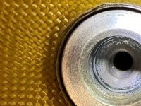
Where did you spot the copper cap? Peering down the outside of the threaded part? In mine, the gap is too narrow for that. Or just down the center hole? Here's a pic of that view. There is an unthreaded section of aluminum maybe 2 mm wide below the thread, and then there is a conical part which seems to be the hole in the top plate.
Just for reference, here's your own thread at htguide, Zaph's blog and another discussion of Zaph's measurements in German (but autotranslate is pretty good these days - if it fails, use deepl).
B&W FST mid
Zaph|Audio
Zaph hat B&W Mitteltöner gemessen
I don't think it is a bucking magnet. The top and bottom plates are beautifully turned, and one wouldn't even need to use any iron below the lower magnet if it were a bucking magnet. It seems to be a very symmetrical design with the middle plate forming the actual gap. Funny thing is, what we can see of the middle plate is just punched. While the rough outside surface probably does not matter and the inside surface is likely turned, the top and bottom surfaces are anything but flat. This leaves a rather random gap between the middle plate and the magnets on either side which might make for rather random flux coupling.
Where did you spot the copper cap? Peering down the outside of the threaded part? In mine, the gap is too narrow for that. Or just down the center hole? Here's a pic of that view. There is an unthreaded section of aluminum maybe 2 mm wide below the thread, and then there is a conical part which seems to be the hole in the top plate.
Attachments

Last edited:
The top plate of the gap in the FST is formed by the first thick turned piece down from the basket. It's underhung and this would match up to the design of all the other FSTs in production. The additional magnets are there for shielding purposes which is very evident when you compare the fringe field of the two I've got. Also the other FST doesn't used a turned part for the bottom plate either, just the top plate. Whatever the arrangement they've chosen this beefs up the motor strength, increases sensitivity and provides some shielding. All of which I am for!
The copper cap is very difficult to see but it's there. Where the threaded section ends, directly beneath this, is the copper cap and below that the start of the pole piece. The only way I could see it was with a very bright torch. Get the light at the correct angle and you can see the glint of a thin sliver of copper coloured material between the two. I'll try taking a picture of it later but I could imagine it being difficult to photograph.
The copper cap is very difficult to see but it's there. Where the threaded section ends, directly beneath this, is the copper cap and below that the start of the pole piece. The only way I could see it was with a very bright torch. Get the light at the correct angle and you can see the glint of a thin sliver of copper coloured material between the two. I'll try taking a picture of it later but I could imagine it being difficult to photograph.
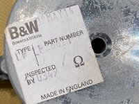
Maybe you got a different FST driver? Mine reads type LP and Part Number LP or LF26611 and it has a turned bottom plate below the lower magnet.
I just shone a torch down the hole and prodded with a pin. There seems to be a cylindrical section of aluminum maybe 2 mm wide below the threading, then a recess, then about 4 mm of a cylindrical section of steel which then becomes the conical section without a further recess or groove. I couldn't make out any copper in the recess between aluminum and steel, but that may be a function of the tolerances of the hole in the copper cap.
I just shone a torch down the hole and prodded with a pin. There seems to be a cylindrical section of aluminum maybe 2 mm wide below the threading, then a recess, then about 4 mm of a cylindrical section of steel which then becomes the conical section without a further recess or groove. I couldn't make out any copper in the recess between aluminum and steel, but that may be a function of the tolerances of the hole in the copper cap.
I looked at a second driver which has much more corrosion but runs fine. Shone down the hole but cannot see copper. It seems the ID of the cylindrical section in the steel is smaller than its counterpart in the aluminum. Going back, same is true for the first driver but maybe less so.
I have included a pic of the back plate and sticker so you can compare to yours. Peering down the hole, it goes all the way from the conical section to the back plate, with an interface somewhere on the way. This is not how I would design a mere bucking magnet.
I have included a pic of the back plate and sticker so you can compare to yours. Peering down the hole, it goes all the way from the conical section to the back plate, with an interface somewhere on the way. This is not how I would design a mere bucking magnet.