Bear with me, its raining here and i‘m quite close to starting on this project so figured some planning might be in order. 😎
Been putting together pieces for a whole new entertainment system/wall for the new house now for a few yrs!
This will be a 2.2 setup, front wall is 13‘ wide, open floor plan back wall is 28’ , vaulted ceilings open to upper loft. here’s where i‘m at……. mains are 10” mtm (eminence delta 10b / b&c de250) stacked on top of eminence lab 15 in a 4 cuft sealed box (one each side)
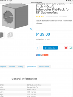
i already have all these components so thats non negotiable, I got the boxes as flat packs because it was so much easier! (See pic)
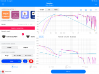
idea was to stack the mains on the subs a little eq and time alignment , call it a day. (see pic for sub fr curve in 4’ sealed, light blue line……the other lines are for the mains (delta 10b) in different box tunings)
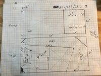
so seeing as theres a 60” wide x 30” deep x 24” tall ‘cabinet’ space just sitting there on each side wasted i thought about trying something like this (see crude drawing) just for the heck of it.…..goals with the experiment are to reduce distortion and make it easier to meet the 98db sensitivity of the mains. I realize it will limit the low end extension some but ill be using a 30hz high pass anyhow you look at it. I wanted to keep the folds to a minimum to keep flow and maybe reduce delay? And another question would be is the 4 cuft box too much to front load……i could smack together a smaller box or pack that one to reduce volume if need be, just trying to keep it simple.
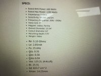
Any help simming or modifying dimensions would be awesome……the external dimensions of cabinet or mouth exit location cannot be changed due to room limitation. (See pic of specs for lab 15, its a special order unit a little different than stock)
appreciate it, Bob
Been putting together pieces for a whole new entertainment system/wall for the new house now for a few yrs!
This will be a 2.2 setup, front wall is 13‘ wide, open floor plan back wall is 28’ , vaulted ceilings open to upper loft. here’s where i‘m at……. mains are 10” mtm (eminence delta 10b / b&c de250) stacked on top of eminence lab 15 in a 4 cuft sealed box (one each side)
i already have all these components so thats non negotiable, I got the boxes as flat packs because it was so much easier! (See pic)
idea was to stack the mains on the subs a little eq and time alignment , call it a day. (see pic for sub fr curve in 4’ sealed, light blue line……the other lines are for the mains (delta 10b) in different box tunings)
so seeing as theres a 60” wide x 30” deep x 24” tall ‘cabinet’ space just sitting there on each side wasted i thought about trying something like this (see crude drawing) just for the heck of it.…..goals with the experiment are to reduce distortion and make it easier to meet the 98db sensitivity of the mains. I realize it will limit the low end extension some but ill be using a 30hz high pass anyhow you look at it. I wanted to keep the folds to a minimum to keep flow and maybe reduce delay? And another question would be is the 4 cuft box too much to front load……i could smack together a smaller box or pack that one to reduce volume if need be, just trying to keep it simple.
Any help simming or modifying dimensions would be awesome……the external dimensions of cabinet or mouth exit location cannot be changed due to room limitation. (See pic of specs for lab 15, its a special order unit a little different than stock)
appreciate it, Bob
Attachments
Last edited:
Bob,
The horn path length will determine it’s delay as well as Fc, the horn cutoff.
Yours looks to be about 7.5’ long, so Fc around 37Hz.
Much of the cabinet space would be wasted on the overly large back chamber and the “X” volume depicted, leaving a small horn mouth, which won’t provide much (if any) low frequency gain compared to simply hanging an exterior port on your 4 cubic foot cabinet.
If you were to use a modified arrangement similar to half of Tom Danley’s Bdeap-32 (Boundary Dependent Air Path) on each side, you could take advantage of the room walls as the final portion of the horn and get more sensitivity than a ported cabinet, but the complexity goes up a bit.

Your 4 cubic foot cabinet with an Fb of 30Hz using a roughly 6.5”x 6.5” x 22” long exterior port should result in near flat response to 30Hz, around 10dB LF gain over the sealed alignment- about four times as loud to your hearing down that low. This sim should still be pretty close to the special order LAB15:

That should be enough to rattle pictures off the wall with an afternoon’s work.
If not enough, you can re-use the port materials for bracing a horn ;^)
Art
The horn path length will determine it’s delay as well as Fc, the horn cutoff.
Yours looks to be about 7.5’ long, so Fc around 37Hz.
Much of the cabinet space would be wasted on the overly large back chamber and the “X” volume depicted, leaving a small horn mouth, which won’t provide much (if any) low frequency gain compared to simply hanging an exterior port on your 4 cubic foot cabinet.
If you were to use a modified arrangement similar to half of Tom Danley’s Bdeap-32 (Boundary Dependent Air Path) on each side, you could take advantage of the room walls as the final portion of the horn and get more sensitivity than a ported cabinet, but the complexity goes up a bit.
Your 4 cubic foot cabinet with an Fb of 30Hz using a roughly 6.5”x 6.5” x 22” long exterior port should result in near flat response to 30Hz, around 10dB LF gain over the sealed alignment- about four times as loud to your hearing down that low. This sim should still be pretty close to the special order LAB15:
That should be enough to rattle pictures off the wall with an afternoon’s work.
If not enough, you can re-use the port materials for bracing a horn ;^)
Art
Thanks Art, It wouldnt be hard to make a rectangular port on the outside of the box for trial and could seal it back if sealed was preferred. I just had all that wasted space and camplos latest thread turn towards folded horns got me all horned up! 🤣
Running it on speakerbox lite even says group delay ported in that configuration doesnt get over 10ms until under 40hz……i can live with that. Phase lines up with mains better too.
Just needed a voice of reason i reckon 😎
Running it on speakerbox lite even says group delay ported in that configuration doesnt get over 10ms until under 40hz……i can live with that. Phase lines up with mains better too.
Just needed a voice of reason i reckon 😎
Check out the BOXPLAN-PARAH workbook at my site below. It could help if you're trying to design a simple horn...
http://www.diysubwoofers.org/sheets/
http://www.diysubwoofers.org/sheets/
