Hello DIY'ers.
I've built speakers before but always used active filters/crossover (miniDSP). So far I've primarily experimented with the FAST designs where I combine a 3-4" full range driver with a woofer and cross at around 250-300Hz.
Recently I've been interested in building more traditional 2-way speakers. I'd like to try a proven design, but instead of building the passive crossover, is there a way to "transform" the passive crossover design into a biquad filter that I can import into the miniDSP?
I'm looking at building a pair of simple and good-value 2-way bookshelf speakers, such as Paul Carmody's Overnight Sensations or the K&T Cheap Trick CT 248 with SEAS drivers.
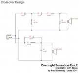
I've attached the crossover design for the Overnight Sensations. Could any of you help me understand how to make the active filter based on these components?
Thanks a lot!
I've built speakers before but always used active filters/crossover (miniDSP). So far I've primarily experimented with the FAST designs where I combine a 3-4" full range driver with a woofer and cross at around 250-300Hz.
Recently I've been interested in building more traditional 2-way speakers. I'd like to try a proven design, but instead of building the passive crossover, is there a way to "transform" the passive crossover design into a biquad filter that I can import into the miniDSP?
I'm looking at building a pair of simple and good-value 2-way bookshelf speakers, such as Paul Carmody's Overnight Sensations or the K&T Cheap Trick CT 248 with SEAS drivers.
I've attached the crossover design for the Overnight Sensations. Could any of you help me understand how to make the active filter based on these components?
Thanks a lot!
Attachments
Hey Soren,
Tuxedocivic (Ryan) did this very thing for me. You can see his measurements and settings here: LINK
The settings he recommended are:
Woofer
BW5 @ 2400
delay = 0.10ms
950hz, -4db, Q = 2
1700hz, -7db, Q = 1.5
4500hz, -5db, Q = 3
Tweeter
BW5 @ 3400hz
Level = -6db
5000hz, +2db, Q = 3
10,000, -2db, Q = 1
18,000, -5db, Q = 2
The settings sounded great. I had the whole thing powered with the miniAMP from miniDSP. I have since burned out one of the Dayton tweeters and Ryan is redoing the crossover for CSS ERT26s.
Kyle
Tuxedocivic (Ryan) did this very thing for me.
Wow, thanks! Great to see this has been done for the overnight sensations. Was the active crossover made for the Dayton or HiVi tweeter?
I was hoping there was a general way of doing this without having to measure each driver. Is it possible to design a digital crossover simply by looking at passive design?
You can do this with any speaker system.
The best way is to use one of the measurement programs and take a differential measurement between crossover input and each of the drivers terminals. This yields an electrical response of each crossover section which you can then import into various design programs to generate an active alternative.
However, the first question that obviously comes up is........since I'm now using an active crossover why can't I improve upon the original passive design? 🙂 Most likely you can.
Cheers,
Dave.
Ryan would have more to say on going from the passive to the active. He aimed to improve it and decided to go off of measurements. That design used the Dayton tweeter.
I am quite excited to see what Ryan produces using the ERT26. The Hivi B4N starts having issues around 4k and that's right where the original xover point was centered. The ERT26 should be able to get much lower than the Dayton. I'll post the results when I get them.
Kyle
I am quite excited to see what Ryan produces using the ERT26. The Hivi B4N starts having issues around 4k and that's right where the original xover point was centered. The ERT26 should be able to get much lower than the Dayton. I'll post the results when I get them.
Kyle
Thanks Dave. The problem with this approach is that I don't have any of the 2way speakers yet, so real measurements of the passive crossover is not a possibility. I could of course just buy the passive components and then build it, but since I already have a miniDSP, and I'm not really sure which 2way design to go after, I thought I could save some time and skip building the passive crossover, and then buy drivers for some different proven designs and see what I like.You can do this with any speaker system.
The best way is to use one of the measurement programs and take a differential measurement between crossover input and each of the drivers terminals. This yields an electrical response of each crossover section which you can then import into various design programs to generate an active alternative.
I've never made a passive crossover before, but I've read hundreds of times how you experts advice us noobs to begin with a proven design, that's why I'd like to "copy" instead of trying to "improve" as you suggest.However, the first question that obviously comes up is........since I'm now using an active crossover why can't I improve upon the original passive design? 🙂 Most likely you can.
Another thing is that the Overnight Sensation is not available as a kit here in Europe (AFAIK). This means I have to buy each of the passive components, and this brings up a whole set of new questions such as "if a 6 ohms resistor is not available, should I then choose a 5.6 or a 6.8 ohm?" and "can I use a 1.0mH or a 1.2mH coil instead of a 1.1mH?"...
If I could go active I was hoping to avoid these dilemmas and also shorten the building process 🙂
Last edited:
Most designers should be able to offer active settings for their designs if you were to ask and they're accessible.
For Kyles pair of OS, I aimed to improve things by lowering and steepening the cross over. As well as flatten things. I thought it turned out pretty good until Kyle hooked things up backwards and forced bass out the tweeter 😛
For Kyles pair of OS, I aimed to improve things by lowering and steepening the cross over. As well as flatten things. I thought it turned out pretty good until Kyle hooked things up backwards and forced bass out the tweeter 😛
If you can measure the driver impedance (or find a *.zma for it that someone else has done), you can simulate the passive crossover and there you have the transfer curve. You don't need any driver frequency response measurements.The problem with this approach is that I don't have any of the 2way speakers yet, so real measurements of the passive crossover is not a possibility.
Most designers should be able to offer active settings for their designs if you were to ask and they're accessible.
For Kyles pair of OS, I aimed to improve things by lowering and steepening the cross over. As well as flatten things. I thought it turned out pretty good until Kyle hooked things up backwards and forced bass out the tweeter 😛
There's nothing worse than crackle-pop-smoke. The miniAMP has some jumpers for configuring the 4 channels, I had left it set in 2x10w+1x20w. 😱
KM
Most designers should be able to offer active settings for their designs if you were to ask and they're accessible.
AllenB said:If you can measure the driver impedance (or find a *.zma for it that someone else has done), you can simulate the passive crossover and there you have the transfer curve. You don't need any driver frequency response measurements.
Thanks for the suggestions. I'll try to ask the designers for active filter settings, and also experiment with impedance measurements.
If you can measure the driver impedance (or find a *.zma for it that someone else has done), you can simulate the passive crossover and there you have the transfer curve. You don't need any driver frequency response measurements.
Doing so gives the following transfer functions:


Pardon my ignorance, but what exactly has been done here? Where have you found the driver impedances? And how did you make these transfer functions? Also, how should I go about designing an active filter based on the transfer functions? Sorry for all the questions, but I'm trying to learn 🙂
Thanks!
It's just the output of a speaker simulation program. Accidentally I had a simulation of both speakers you mentioned, so it was no big deal. That means the program knows cabinet, passive crossover and driver data of both speakers and is able to simulate some results. The curves show the transfer function of the passive crossover. If you manage to get the same transfer function using a digital crossover, then you have reached the goal of converting a passive loudspeaker to an active equivalent.
It's just the output of a speaker simulation program. Accidentally I had a simulation of both speakers you mentioned, so it was no big deal. That means the program knows cabinet, passive crossover and driver data of both speakers and is able to simulate some results. The curves show the transfer function of the passive crossover. If you manage to get the same transfer function using a digital crossover, then you have reached the goal of converting a passive loudspeaker to an active equivalent.
I see. Thanks for the explanation. What simulation software have you used here?
I've never made a passive crossover before, but I've read hundreds of times how you experts advice us noobs to begin with a proven design, that's why I'd like to "copy" instead of trying to "improve" as you suggest.
There is no active OS. The OS is passive and an active equivalent is a different design, except in general parameters such as choice of crossover frequency.
I was hoping there was a general way of doing this without having to measure each driver. Is it possible to design a digital crossover simply by looking at passive design?
I have no experience with DSP but I think I know how things work, so...
1) From passive XO you can see the L-PAD. This tells you how much you want to pad down the tweeter because it is more sensitive than the woofer. Tuxedocivic gave a hint that it is -6dB (the level of the tweeter). But actually you can use ears to find the level you are comfortable with.
2) Any popular speaker project will tell you what is the XO frequency (here I think 4 kHz) and what is the acoustical filter (here I think LR4). You can copy this setup then later compare with what Tuxedocivic has done, because the benefit of active XO over passive XO is that you can bring the XO lower by steepening the slope (Here Tuxedocivic did it with BW5) without ill effect of high order passive filters.
3) To flatten the response you can use the parametric equalizer. Tuxedocivic already gave you a hint about frequency points where you need to boost or cut and the Q. You can see the response measurement of the drivers to visualize the dips and the peaks.
Do this step by step, from the most critical peak. You can bypass your setting to hear whether your EQ really hit on the right target or not.
4) Phase and delay. This is the most critical imo. The good thing about LR4 is that there is "no" issue with phase. I don't know whether a novice can set the delay based on ears. But you can try. If you switch the speaker cable polarity, a deep null will be heard as the signal being greatly attenuated. This is a good condition of being in phase at XO frequency.
5) If you know how things work and especially if you have good ears, you can try various setup relatively quickly and then can just trust your ears. This is the benefit of such active XO.
ADD:
In the passive XO for the woofer you can see a capacitor across the inductor. This is to build a deep notch at high frequency so as to steepen the filter to meet LR4. This is not an easy thing to do with your DSP. I don't know how the PEQ in the MiniDSP work but you can try. Simply listen to the woofer, does it have intolerable peak/distortion. If so, pay attention to the woofer PEQ setup above XO frequency. If you still cannot bear the peak/distortion then you should consider steeper crossover. Or just compare to what Tuxedocivic has done.
Last edited:
Thanks for the input Jay. Very appreciated!
Just one thing I'm not sure about:
Is the crossover always the same frequency for the two drivers crossing? So if it's at 4kHz then it's at 4kHz for both the woofer and the tweeter? The reason I ask is that in Tuxedocivic's active filter design it says:
Woofer: BW5 @ 2400Hz
Tweeter: BW5 @ 3400hz
Perhaps a typo?
Just one thing I'm not sure about:
Jay said:Any popular speaker project will tell you what is the XO frequency (here I think 4 kHz) and what is the acoustical filter (here I think LR4).
Is the crossover always the same frequency for the two drivers crossing? So if it's at 4kHz then it's at 4kHz for both the woofer and the tweeter? The reason I ask is that in Tuxedocivic's active filter design it says:
Woofer: BW5 @ 2400Hz
Tweeter: BW5 @ 3400hz
Perhaps a typo?
BW5 appears to be a typo for BW6, unless MiniDsp has some filter I have never heard of before😉.Just one thing I'm not sure about:
Is the crossover always the same frequency for the two drivers crossing? So if it's at 4kHz then it's at 4kHz for both the woofer and the tweeter? The reason I ask is that in Tuxedocivic's active filter design it says:
Woofer: BW5 @ 2400Hz
Tweeter: BW5 @ 3400hz
Perhaps a typo?
Underlapping ( leaving an electrical "hole") crossover points is often required to get the desired acoustical crossover response.
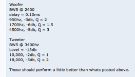
You should note that Tuxedocivic later posted new settings that are quite different than the ones posted previously after actually testing the acoustic response. I have posted them below.
Whether they match the acoustic response of the original crossover is unknown without seeing the individual response of the low and high driver output of using the passive crossover.
Duplicating the electrical response of a passive crossover ignores the speaker parameter interaction, one really needs to measure the acoustical response to duplicate the acoustical response curves.
That said, since time alignment with passive components is difficult to implement, but easy with DSP, one can generally improve response using DSP compared to passive.
Without good test gear and knowledge of how to use it, one never knows how far off simulations are.
Art
Attachments
Thanks for the comments. I learned something today 🙂
PROTOTYPING A 4-WAY OPEN-BAFFLE SPEAKER WITH THE MINIDSP 2×4
REFINING A 4-WAY OPEN-BAFFLE SPEAKER WITH THE MINIDSP 2×4
I begin to understand the problem with the idea I had. You can't make a digital filter simply based on a passive crossover design that you see on the computer screen.Duplicating the electrical response of a passive crossover ignores the speaker parameter interaction, one really needs to measure the acoustical response to duplicate the acoustical response curves.
I need a microphone and I need to read more about the miniDSP possibilities I think:That said, since time alignment with passive components is difficult to implement, but easy with DSP, one can generally improve response using DSP compared to passive.
Without good test gear and knowledge of how to use it, one never knows how far off simulations are.
PROTOTYPING A 4-WAY OPEN-BAFFLE SPEAKER WITH THE MINIDSP 2×4
REFINING A 4-WAY OPEN-BAFFLE SPEAKER WITH THE MINIDSP 2×4
Is the crossover always the same frequency for the two drivers crossing? So if it's at 4kHz then it's at 4kHz for both the woofer and the tweeter? The reason I ask is that in Tuxedocivic's active filter design it says:
Woofer: BW5 @ 2400Hz
Tweeter: BW5 @ 3400hz
Perhaps a typo?
If the frequency is different then it is not crossover but passover 😀
There is standard terminology for crossover frequency, especially for standard filter (LR, Bessel, Butterworth, etc) such as the -3dB position of the acoustical roll off.
If you apply the same slope type for both tweeter and woofer (symmetry) then they should cross somewhere around -3dB to -6dB (acoustically) but not too much. Especially for steep slope such as BW6 it is not a good thing to cross at 2K4 for woofer and 3K4 for tweeter. I'm here assuming that MiniDSP uses the standard filter terminologies in the software.
BTW, +3dB or -6dB at XO frequency is not unusual. But for standard LR4 it should be theoretically 0dB (flat).
From the passive XO you can see that the woofer has issues around the XO, which is why the capacitor across the inductor. I don't know how the inside of the MiniDSP work, but it seems similar to analog. In this case you cannot do tricks like in passive XO. So the 2K4 is possible as a active XO trick but is not a good approach imo.
So you see, DSP is not as easy and simple as people might think. Yes, it makes life simpler for those who doesn't know much about passive design. For those who knows much, may be not.
- Status
- Not open for further replies.
- Home
- Loudspeakers
- Multi-Way
- From passive to active filter