I've been messing around with a giant two-chassis 845 SE amp based on Grover Gardner's circuit. It worked o.k. as I initially built it, but didn't sound as good as I wanted and 8.5mv hum was too much for me. Unfortunately, my extensive mods are giving me about 40x the hum I had before!
I went from a single filament supply for all the tubes (845s, 6l6s, and a 6n7) to separate supplies for each 845 and one for the 6.3V tubes (the single supply was a relic of the way I bought the project--not by choice). The 845 supplies now use separate secondaries from a big old Hammond 1143X (thanks, Ebay!) running into full bridges of shottkys, then CRCRC followed by a common mode choke. The center taps of the secondaries are tied off. The negative leg of each 845 socket connects to a 100 ohm resistor to ground (test points on each side for biasing). Between the legs of each 10v supply (at the socket), I'm getting 1.1mv or so of ripple. But, I'm getting like 2.5V of ripple across the 100 ohm resistor?
I get that same result on the 100r resistor with or without the B+ on. When I connect the B+, it shows 1-2mv of ripple where connected to the OPT primary, but then 12VAC at the 845 plate? Bias supply shows 1-2mv of ripple. (All just according to my DMM).
I'm assuming I'm not understanding something about how I built these filament supplies. But, for context, the other changes I made include adding PS capacitance (not excessive and same first cap--the reservoirs were probably too small before), separating the signal and chassis grounds in a larger umbilical (they were joined in the signal chassis for lack of wires before, they are connected in the PS chassis), and connecting the speaker ground to signal ground with big 100 ohm resistors (they floated before). The 6.3V supply is also DC from its own transformer, but less filtering and with the negative at signal ground.
Thanks for any help!
Paul
Here is one leg of the filament supply and the amp circuit. (Resistor values might be a bit different--I'm at like 910V B+).
I haven't drawn the PS. The B+ is on a mechanical timer, rectified by 3B28s. 50uf first, a big choke, then a half dozen 470uf caps in two banks of three in series. For B+2, another choke, then UF4007s and 100r resistors into separate banks (3 series 330uf/side), dropping resistors, and B+3 (3 series 100uf/side). All have film bypass caps. Bias is out of a separate transformer and tube rectified CRC. The 6.3v supply is yet another transformer with a full schottky bridge into 20kuf, .1r, 20kuf. And, of course, there is the filament transformer for the 3B28s. (The bias supply rectifier is heated from the bias transformer).
I've attached Grover's PS schematic just for posterity. Mine isn't so different aside from the additional choke, shared B+, and different resistor values for the different b+ voltage.
So, the umbilical has 9 wires: B+, bias (about -160v before the pots), 4 wires for the 845 filaments, 6.3V DC+, signal ground, & chassis ground. Part of why I'm running the 6.3 filaments on DC is because I've only got 9 pins for these big old Amphenol connectors. I also thought it wouldn't hurt if there was no AC in the umbilical.
One other note--I'm only getting about 5.85V on the 6.3V filament supply. I'm hoping that is good enough, as this old Chicago transformer was expensive and I cut a big hole in the chassis with it in mind.
The signal supply is unchanged from when it was working before.
Attachments
Last edited:
I built a pair of Grover's 845 amps 18 years ago and have listened to them with great enjoyment ever since. In my amps, the signal grounding is done via a bus of 14 gauge wire that runs around the amp in an open loop, starting at a point near where 120VAC comes in to the chassis and attaches the AC ground to the chassis, thence to CT of the power transformer, thence to all the power supply grounds, etc. until all the necessary grounds have been attached to the bus. The bus and the AC ground are attached to the chassis at a single point. (Green wire from AC runs out of amp, bus wire runs around the inside of the amp.
My first suspicion is that having signal and AC grounds inside the umbilical completes a ground loop, though I would have to see everything in person to tell. In any event, having the high current 10V and 6V filaments wires side by side with all the grounds probably induces some coupling that may be the source of the problem. My first inclination is to take the AC ground out of the umbilical and see what happens. Be very careful about what you touch if you try this.
My first suspicion is that having signal and AC grounds inside the umbilical completes a ground loop, though I would have to see everything in person to tell. In any event, having the high current 10V and 6V filaments wires side by side with all the grounds probably induces some coupling that may be the source of the problem. My first inclination is to take the AC ground out of the umbilical and see what happens. Be very careful about what you touch if you try this.
Last edited:
I built two versions of these amps many years ago. Both were monoblock pairs. The first version used all separate transformers for HV, bias, 6.3 volt and 10 volt filaments. They were dead quiet. The current owner has used them for over 20 years without a single issue.
For the second version, I decided to simplify things and ordered a pair of 120/12/6.3 transformers from Electraprint for the bias and filament supplies. I NEVER got them quiet. It was better after I peeled off the bias supply to a separate transformer, but they were still never satisfactory. I suspect poor shielding in the filament windings, cross-coupling or something of that nature.
I question the use of 3B28s, not sure why they're needed. The original power supply was a single B+ using full-wave UF4007's in series. Worked perfectly. I'm not sure it's a good idea to use 3B28s with cap input, and they're notorious for generating RF noise. I have no idea if that's an issue here or not.
As Roger suggests, maybe a ground loop issue between the power supply and the signal chassis.
Other than that, I wish I could be more helpful.
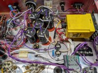
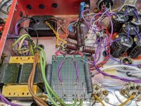
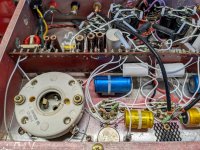
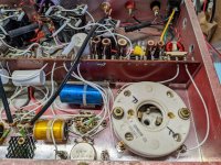
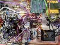
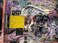
I spent a while staring at it and still can't figure it out. I'll post a bunch of pics. If you can make sense of these rats nests, you are a great deal smarter than I am!
The signal circuitry is unchanged from when it ran with 8.5mv of hum. So is the bias supply, but I did move it.
There isn't a loop between the signal and chassis ground between the PS and the signal supply. The signal chassis ground is connected to chassis ground in the PS. The signal chassis signal ground connects to the signal star ground in the PS, which is connected to a switch between a ground loop breaker and a short to chassis ground. That is the only place the signal and chassis grounds are connected.
I think I'm chasing a big grounding goof up. This amount of hum doesn't seem like a layout problem, especially because so much of this is the same as it was before. The only weird measurements I'm seeing are A) as mentioned above, ripple at the 845 plates but NOT at the other and of the primary winding, and B) a split second of continuity between the 845 plates and ground. After that split second, everything measures as normal. There definitely isn't a short to ground as the B+ is sitting right where it should be (and this is not at all a stiff supply!).
I probably should have done what I long ago said when picking this chassis and up and torn it apart to make monoblocks--at least before I dumped all this $$ into these brand new caps that are now stuck down with adhesive.
As far as the 3B28s--I'm just using them because they were in the PS chassis as I bought it and they look cool. If I tear all of this apart to build monoblocks I promise I'll use SS rectifiers. While I added considerable capacitance everywhere else, the first cap in the B+ is the same 50uf it was back when I was only getting 8.5mv of hum.
Paul
Attachments
-
 PXL_20220313_214907981.jpg696.6 KB · Views: 80
 -
 PXL_20220313_214911124.MP.jpg672.5 KB · Views: 67
 -
 PXL_20220313_214918181.jpg619.1 KB · Views: 66
 -
 PXL_20220313_214922900.jpg674.3 KB · Views: 63
 -
 PXL_20220313_214936931.jpg802.6 KB · Views: 79
 -
 PXL_20220313_214940596.MP.jpg747 KB · Views: 79
 -
 PXL_20220313_215013724.jpg741.7 KB · Views: 89
 -
 PXL_20220313_215022173.MP.jpg736.9 KB · Views: 103
I don't think the location/grounding of the PS bypass caps on the B+2 and B+3 (the big white ones) is ideal. So, I disconnected them all. No change. I also dropped to half of the B+ capacitance (2nd cap). No change. That center bolt in the signal chassis goes to a toroidal choke that is situated between the OPTs. Moving it around doesn't do anything.
Paul
Paul
Okay, thanks for the pics. A couple of things:
How many 6N7s are you using? Unfortunately, my schematic doesn't make clear that each channel should use a 6N7 run in parallel mode. That's the way a 6N7 is used as a voltage amplifier. I can't tell from the sockets but it looks like maybe you're using half a 6N7 per channel. That makes the plate resistance way too high so the plate load will be too low, etc etc. Maybe why it doesn't sound good.
Ground for the signal chassis should be at the input. A solid copper buss would be ideal, but grounding to a star somewhere else on the chassis may be causing a hum problem.
Cap size etc etc shouldn't really make any difference.
If you can power up the filaments without the HV, check for AC ripple there. Put the 845s in and see if you hear any hum. If the 10vdc supply is built properly there shouldn't be any.
The toroid choke could be injecting noise into the circuit. I've never used one so I don't know, but I would be suspicious.
Ironically, I was just looking at your schematic and noticed the 2x in front of the 6n7! I had started with Roger's schematic, which doesn't show that. So, yeah-Wrong all along! Not sure I can squeeze in another socket or that I have enough filament current. So .... Having spent a bunch of time and $$ to turn an amp that more or less worked into one that doesn't, I suppose it is time to start over.
I am contemplating whether to move over to George's circuit and use some sand to get the power these OPTs were originally designed for (these are the monster AES/Cary transformers). But assuming I stick with this schematic, in a perfect world, what would the rest of the PS look like?
I am contemplating whether to move over to George's circuit and use some sand to get the power these OPTs were originally designed for (these are the monster AES/Cary transformers). But assuming I stick with this schematic, in a perfect world, what would the rest of the PS look like?
- Should I stay with the linear filament supplies on the 845s? It looks easy to get 12V or 15V transformers and the cheap regulated supplies from Ebay. Easier than playing with different combos of low value resistors each time until I get the voltage right, as I've been doing. But, I don't want them to fail and kill an expensive tube.
- Preferences for filament transformers?
- Is it riskier from a noise perspective to use the same transformer for bias and one or both filament supplies?
- Why not run a second choke for the B+2?
- I assume I want to make some effort to delay the B+. I don't know that I want to buy another one of these mechanical timers. Are thermistors on the B+ transformer primary enough?
Sorry about the confusion over the 6N7. Who is George and what is the circuit? Here are my suggestions:
Rod Coleman's stereo 845 regulated filament board is $43 plus shipping (whatever that is). You provide a raw DC supply.
http://www.lyrima.co.uk/dhtreg/dhtRegIntro.html
For the 6.3 volt filaments, it won't hurt to run a tightly twisted pair in the umbilical. I've done it and there's no issue. Much easier and you won't get the drop from the rectification.
You don't need a second choke if the first one is sufficient.
But here's what I would do:
For the power supply chassis:
-HV transformer with UL4007, like 5 in series per leg with balancing resistors, first cap, choke (or pair of chokes for split supply to each channel)
-6.3 VAC at 5 amps
-12-15 VAC with bridge rectifier for Coleman boards
-Reverse 6.3 VAC/500mA filament transformer running from main 6.3 transformer, single reverse diode, filtering, for bias supply.
-Two power switches. Turn on filaments and bias supply, then HV after warmup.
For signal chassis:
-Decoupling caps for HV supply, followed by decoupling stages for the rest.
-bias pots, etc.
-Coleman regulator boards (if you have room).
If you want to add a second choke you can but get a standard frame choke, 10H at 100mA or something like that.
Since you're short a socket, you could sub a 6C8G for the input tube. Double the plate resistor value and play with cathode resistor value until you get it running per the data sheet. Just a thought.
Don't know if this helps! Keep us posted.
One other caution: do not use printed circuit boards anywhere in a power supply. Electrical discharges occur at sharp points and edges. The slightest discharge is a very noisy resistor or worse. When I first built my amps I put the diode strings on printed circuit board............bout as dumb as anything a physicist has ever done.............👎👎🙄
Interesting. I was asking about starting over as monos, so that would mean no umbilical needs. But if the 6C8G were to work, I suppose I'd be back to trying to figure out this hum issue!
Decisions .... Maybe I'll see if my power transformers seem like they'll work for monos before going farther into getting it working again as a two-chassis stereo amp.
Paul
Decisions .... Maybe I'll see if my power transformers seem like they'll work for monos before going farther into getting it working again as a two-chassis stereo amp.
Paul
All of the Quad ESL parts are on pcbs, and we're talking several kV there. Just follow the creepage and clearance rules.One other caution: do not use printed circuit boards anywhere in a power supply. Electrical discharges occur at sharp points and edges. The slightest discharge is a very noisy resistor or worse. When I first built my amps I put the diode strings on printed circuit board............bout as dumb as anything a physicist has ever done.............👎👎🙄
https://resources.pcb.cadence.com/b...-clearance-standards-in-circuit-board-layouts
Last edited:
Interesting. I was asking about starting over as monos, so that would mean no umbilical needs. But if the 6C8G were to work, I suppose I'd be back to trying to figure out this hum issue!
Decisions .... Maybe I'll see if my power transformers seem like they'll work for monos before going farther into getting it working again as a two-chassis stereo amp.
Paul
Oh, I see.
Regarding PCB's, do it if you want. Watching the electrical breakdown in air at the corners of PCB traces with 1,100V was plenty for me to say not no but hell no. I am at 7,000 feet elevation, may have an effect. YMMV
Those little boards are only the filament supplies. It is just an easy way to hold the diodes together, and I'm imagining that it isn't a problem at 6.3 and 10V.
I am curious to know how folks prefer to physically mount the diodes for this HV bridge. I assume terminal strips. I might pull some out of an old Tek 'scope. If I rebuild these in to monoblocks, I'll probably be more at 1200V with those transformers than the 900V I'm at with this one.
And Roger, I'm only a little lower in Denver! I messaged you years ago when when you were trying to figure out what to do with your set of these! I didn't year back and am clearly still in the process of rolling my own!
One of the benefits of rebuilding is that I'm sure I can make them safer. I found better top caps and ire, but don't love what is on the 3B28s. I bought some super nice Belden wind turbine cable for the new umbilical and then covered it in a heavy tinned copper braid. I'd still rather have all that high voltage contained inside a chassis. And I don't love that the signal chassis chassis ground has to go through so many connections to get to the wall.
Paul
Hi Paul: I have finally come to grips with the notion of doing without my 845 amps. I completed a pair of Williamson amps last spring so now I can do without the 845's.
Now, the printed circuit boards I was referring to was the perf board from Radio Shack I bought 20 years ago for miscellaneous projects, typically the diode based current sources that Bottlehead developed.. I can guarantee that you will get arcing from diode to diode if you use that. My diodes are now simply soldered together in a V-string and then covered with the WEICO insulation tubing, supposed to be good to 8,000 Volts, and screwed to the power transformer and soldered at the positive terminal of the first PS capacitor. Cute little bridge in the air hasn't been a problem of any sort in 18 years. If you want to try the WEICO insulation tubing send me a PM with your mailing address and I'll send you some. Also, if you would like to hear them before the wrecking ball hits them, come down for a listen. I am just west of I-25 near the south entrance to the Air Force Academy so you wouldn't have to deal with city traffic to do so.
Now, the printed circuit boards I was referring to was the perf board from Radio Shack I bought 20 years ago for miscellaneous projects, typically the diode based current sources that Bottlehead developed.. I can guarantee that you will get arcing from diode to diode if you use that. My diodes are now simply soldered together in a V-string and then covered with the WEICO insulation tubing, supposed to be good to 8,000 Volts, and screwed to the power transformer and soldered at the positive terminal of the first PS capacitor. Cute little bridge in the air hasn't been a problem of any sort in 18 years. If you want to try the WEICO insulation tubing send me a PM with your mailing address and I'll send you some. Also, if you would like to hear them before the wrecking ball hits them, come down for a listen. I am just west of I-25 near the south entrance to the Air Force Academy so you wouldn't have to deal with city traffic to do so.
- Home
- Amplifiers
- Tubes / Valves
- From 8.5mv of hum to 330mv .... oops.