Hello everyone. I finally put together a temporary supply for the 180AD module so I could test it out with a sub real quick. I connected everything as it should be and had music playing for a little bit using one channel of my ipod as the source. I used insulated fast-on connectors for supply connections, a hacked cd-rom drive cable for the input signal (works nicely with the pins on the board), and alligator clip leads to attach the speaker to the output tabs and the on pin to the supply ground to turn the module on. The rails of the supply were exactly at +/-45V with an Avel 225VA transformer using 33VAC secondaries. Anyways, I had it up and running into a disposable 8 ohm test speaker and it was playing fine for a little bit. I went to move the module and touched the back of the PCB and the sound cuts out and I see a little plume of smoke coming from the module. I immediately unplugged the power cord and disconnected the on pin from the supply ground. Needless to say I was a little scared/angry that I caused some serious damage to the module. Upon closer inspection it appears that I only fried R29, and boy is it completely burnt.
Does anyone know what happened or what R29's purpose is? It's possible I shorted the output and that caused it to fry but I really don't know. Can anyone tell me what value R29 is so I can try to replace it and see if the module still works?
Does anyone know what happened or what R29's purpose is? It's possible I shorted the output and that caused it to fry but I really don't know. Can anyone tell me what value R29 is so I can try to replace it and see if the module still works?
BWRX said:Hello everyone. I finally put together a temporary supply for the 180AD module so I could test it out with a sub real quick. I connected everything as it should be and had music playing for a little bit using one channel of my ipod as the source. I used insulated fast-on connectors for supply connections, a hacked cd-rom drive cable for the input signal (works nicely with the pins on the board), and alligator clip leads to attach the speaker to the output tabs and the on pin to the supply ground to turn the module on. The rails of the supply were exactly at +/-45V with an Avel 225VA transformer using 33VAC secondaries. Anyways, I had it up and running into a disposable 8 ohm test speaker and it was playing fine for a little bit. I went to move the module and touched the back of the PCB and the sound cuts out and I see a little plume of smoke coming from the module. I immediately unplugged the power cord and disconnected the on pin from the supply ground. Needless to say I was a little scared/angry that I caused some serious damage to the module. Upon closer inspection it appears that I only fried R29, and boy is it completely burnt.
Does anyone know what happened or what R29's purpose is? It's possible I shorted the output and that caused it to fry but I really don't know. Can anyone tell me what value R29 is so I can try to replace it and see if the module still works?
Bad luck...you can't touch with your fingers the solder side of the PCB when the amp is powered ON. You will create locally a short circuit, and when you are unlucky the amp will burn down....
As in this case.
R29 is a part of the short-circuit protection, so the Fets will also be burned and probably some more components in the driver circuit.
Regards,
Jan-Peter
Re: Re: Fried R29 on UcD180AD
Thanks for the information Jan-Peter. One thing I don't quite understand is how my finger accidentally touching the parts on the PCB for a fraction of a second could cause a short circuit serious enough to fry a component like it did. My fingers weren't greasy or damp or anything, as I had just washed my hands. Also, I can touch exposed components on my amp3 PCB and nothing happens at all (maybe a buzz from the speakers if I touch the input signal pins but that's about it). Granted the amp3 only uses a 14V supply, but I can touch my fingers to a cap charged to 45V and not get shocked either.
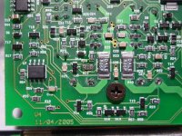
If R29 is part of the short circuit protection then it's more likely that the alligator clip leads touched at the output tabs on the module. I didn't see them spark or anything so I can't say with any certainty if they did or not. All I know is R29 is toast. Check out the attached photo. All the other parts appear to be intact.
I'd still like to try and replace R29 to see if I can save myself the pain and agony of waiting to buy another module, so would someone be kind enough to tell me what value resistor R29 is?
Jan-Peter said:you can't touch with your fingers the solder side of the PCB when the amp is powered ON. You will create locally a short circuit, and when you are unlucky the amp will burn down....
R29 is a part of the short-circuit protection, so the Fets will also be burned and probably some more components in the driver circuit.
Thanks for the information Jan-Peter. One thing I don't quite understand is how my finger accidentally touching the parts on the PCB for a fraction of a second could cause a short circuit serious enough to fry a component like it did. My fingers weren't greasy or damp or anything, as I had just washed my hands. Also, I can touch exposed components on my amp3 PCB and nothing happens at all (maybe a buzz from the speakers if I touch the input signal pins but that's about it). Granted the amp3 only uses a 14V supply, but I can touch my fingers to a cap charged to 45V and not get shocked either.
If R29 is part of the short circuit protection then it's more likely that the alligator clip leads touched at the output tabs on the module. I didn't see them spark or anything so I can't say with any certainty if they did or not. All I know is R29 is toast. Check out the attached photo. All the other parts appear to be intact.
I'd still like to try and replace R29 to see if I can save myself the pain and agony of waiting to buy another module, so would someone be kind enough to tell me what value resistor R29 is?
Attachments
Hi Brian,
My UCD180's arrived today, judging by the code (1001) and my meter R29 is 1k on my boards
Sorry to hear about your bad luck, I hope you can fix them
Does the resistor actually measure open circuit?
My UCD180's arrived today, judging by the code (1001) and my meter R29 is 1k on my boards
Sorry to hear about your bad luck, I hope you can fix them
Does the resistor actually measure open circuit?
Thanks t. It actually doesn't measure as an open circuit. My meter measures 1.158kohm, but it gradually increases to that value which indicates that it's measuring more than just resistance. I actually saw smoke and you can see it obviously came from R29 from the photo. The resistor's thick film was vaporized  and released that all too pleasant burning electrical aroma
With my meter on the diode setting I measure 0.64V between the (positive lead) lower pin and the (negative lead) upper pin of T15, and 0.606 between the (positive lead) middle pin and the (negative lead) upper pin of T15. That's looks good to me, and whatever current fried R29 had to be going through T15, so I'm hoping the other parts are all still ok.
and released that all too pleasant burning electrical aroma With my meter on the diode setting I measure 0.64V between the (positive lead) lower pin and the (negative lead) upper pin of T15, and 0.606 between the (positive lead) middle pin and the (negative lead) upper pin of T15. That's looks good to me, and whatever current fried R29 had to be going through T15, so I'm hoping the other parts are all still ok.
Well good luck Brian!
Lets just hope that tiny resistor burned out before anything else if its part of the short circuit protection
I also had the Amp3 so I'm looking forward to trying these modules, I've got another half dozen different diy amps to compare them against
Lets just hope that tiny resistor burned out before anything else if its part of the short circuit protection
I also had the Amp3 so I'm looking forward to trying these modules, I've got another half dozen different diy amps to compare them against
BWRX,
As you can see on the bottem of the PCB T15 is connected with 1K to power resistor 0.05 R39. When the voltage accross R39 is more as 0.6V, transistor T15 starts to conduct. This is the top side of the current protection. Try to remove R30. And power the UcD180 again, when you are VERY LUCKY, only R39 is fried. Otherwise you have to replace the fet's and probably some driver transistors.
For checking if the amp works, it's unessecary that there is a current protection.
Jan-Peter
Hi,
A series light bulb with your supply might be a brilliant idea.
Something to consider is that if the mosfets are blown you're taking an extra chance at smoking even more driver components. I'd check the Fets with a meter first and if they are blown just replace all the driver semiconductors at once. If the meter say's they're OK (not shorted pin to pin) most likely you'll be laughing.
If you don't have a plug BTW, just solder it to the pin, alligator clips seem deadly here. I'm pretty sure it's the same plug as a floppy drive takes so you know where to cut one off of, old computer PSU's should have at least one or two of them.
Good luck.
C.
Adding to Chris' post I'd like to add that if mosfet's fail they always fail as a short-circuit, either between all pins, or two pins. So you can easily check with a multimeter prior to powering up the amp whether they are still okay. If both are defective you're simply shortcircuiting your power-supply, which isn't a good idea 😱
Best regards,
Sander Sassen
http://www.hardwareanalysis.com
Best regards,
Sander Sassen
http://www.hardwareanalysis.com
Sorry to bring this back from the dead but I'm finally getting around to repairing my UCD180. I've removed the output FETs because they need to be replaced. I've also removed the remains of R29 and cleaned up the board the best I could. There was a small crater left underneath R29 because it got hot enough to burn into the PCB
Anyway, I can scrounge a 1k 0805 resistor but am having a harder time finding a suitable replacement for the STP14NF10FP FETs. These were obviously chosen very carefully as they have the lowest gate charge capacitance I've seen (by a factor of at least 2!), very good rise and delay and rise and fall times, and excellent reverse recovery characteristics when compared to FETs with similar ratings. They do have a higher Rds(on), however, but you can't have everything...
If I opted to use a regular TO-220 package with a mica insulator instead of a TO-220 fullpack would that be acceptable? There are comparable TO-220 pacakge FETs out there with better thermal characteristics (obviously) but I remember reading that the capacitance between the tab of the FET and the heatsink can have an effect on the performance of the amp. Would the higher stray capacitance between the drain and ground cause excessive ringing or have some other detrimental effect?
Here are the replacement FETs I've been considering in this order:
1) IRFB4212 - TO-220AB $2.08/1 - 100V, 18A, 72.5mohm, 15nC Qg, 41ns trr, 3-5Vgsth
2) IRF520V - TO220AB $1.86/1 - 100V, 9.6A, 165mohm, 22nC Qg, 83ns trr, 2-4Vgsth
3) IRLI520N - TO-220FP $1.75/1 - 100V, 8.1A, 180mohm, 20nC Qg, 110ns trr, 1-2Vgsth
4) ?
STP14NF10FP - TO-220FP $?.?? - 100V, 10A, 115mohm, 15.5nC Qg, 90ns trr, 2-4Vgsth
Hi Brian,
I think you're going to run into trouble if you make a change of mosfets. The drivers and snubbers are all optimal for what they currently use, and your intuition is likely correct that you'll see all kinds of oddities if you do change them.
Your possible choice of #3, logic level is it? Don't even consider it!
Here's a real performer that might meet your needs and samples are available from the good folks at Fairchild, it is optimized for high speed switching.
http://www.fairchildsemi.com/ds/FD/FDP3672.pdf
All the same, I could concentrate my efforts on finding an exact replacement just to make your life easy.
Whoops! The IRLI520N is logic level. Nice catch.
That FDP3672 has some very nice specs and it's cheap to boot, but it isn't in stock anywhere.
I searched for STP14NF10FP at mouser and it returned an entry for the Fairchild FQPF17N08, which is pretty decent spec-wise as well and is in stock and cheap 🙂 I might have to give that a try when I put in an order at Mouser.
Hmmm, even that is not an exact drop in type replacement, a few crucial specs differ, for example, it's only an 80V part, I'd rule it out on that alone!
Here is probably your best alternative, with the insulator of course. 🙂
http://nunext.nuhorizons.com/NuNext/servlet/NUHOnlineOrderingPartSearch?mode=Search
Given the mirrored layout, with T-sink grounded/bypassed seperator, I don't think I'd concern myself with any possible increase in EMI brought on by the change in package. As a bonus you get a slightly higher current rating (not that it matters).
Did you also verify your driver transistors??
EDIT: Ah, I see that link is useless.
Try going to http://nunext.nuhorizons.com and searching for STP14NF10
No, it's not a drop in, but nothing is besides the STP14NF10FP.
I'd have use maximium rail voltages of about 35V because of the 80V rating.
I checked the base emitter junctions, base collector junctions, and diodes and they all appear to be fine. It seems I just fried that one resistor and both output FETs.
The standard package STP14NF10 would surely work fine. I might just end up getting a couple of those as well as the #1 choice I mentioned earlier and see what happens!
BWRX said:No, it's not a drop in, but nothing is besides the STP14NF10FP.
I'd have use maximium rail voltages of about 35V because of the 80V rating.
I checked the base emitter junctions, base collector junctions, and diodes and they all appear to be fine. It seems I just fried that one resistor and both output FETs.
The standard package STP14NF10 would surely work fine. I might just end up getting a couple of those as well as the #1 choice I mentioned earlier and see what happens!
Hi,
Send me your address by email and we will ship you some STP14NF12FP (we moved to 120V FETs) for free by post.
Regards,
Jan-Peter
Jan-Peter, you've got mail. I'd be more than happy to pay for a pair since I destroyed them in the first place. Either way, thank you very much for the offer!
BWRX said:Jan-Peter, you've got mail. I'd be more than happy to pay for a pair since I destroyed them in the first place. Either way, thank you very much for the offer!
Brian,
We will ship you this week a couple of free STP samples!
Good luck with the repair.
REgards,
Jan-Peter
Hypex
I just want to add my 2 cents worth. The guys at Hypex are ultra responsive to customer needs. We ordered a UCD180 for evaluation for one of our customers (They are still "evaluating" 6 months later. I blew the driver PCB and FETs, Jan-Peter sent us repalcements and in very short time. My UCD400 blew the FETs and Jan-Peter responded.
Thanks Jan-Peter for your great service.
I did try numerous FETs in both the UCD180 and UCD400 modules and they all have worked well.
Of course the UCD400 I used 150v fets and the 1UCD80 I used both 100 and 150v fets. I have only run the UCD180 at a max of +/-38v and the UCD400 at +/-60v. These supply rails do not allow the modules to attain advertised power but that was not my concern. I only needed a fixed amount of power.
100v FETs:
FDP3682
FQP33N10
IRFB4212
The STPF14NF10P is hard to get hold of
150/200v FETs:
FDP42AN15A0 used by Hypex
FDP38N20 less money than the above and works fine $0.70
IRFB23N15D $0.66
The FDP42AN15A0 is close to $1.00 in the USA
Yes each type of FET does exibit slighty different THD values on our Audio Precisions, but nothing that I would worry about. One could easily trim the current resistor on the UCD180 and adjust the trim pot on the UCD400 to compensate for different FET characteristics. However I do not recommend this to anyone who does not have the required equipment. This is easy to do with the APs as you can repeat sweep the THD run and adjust the resistor until the "target" THD is attained.
On the UCD180 the IRFB4212 performed the same as the STMicro parts. The two Fairchild FETs with slightly higher gate charge exibited slightly higher THD. (If an increase of less than 0.01% is anything to worry about!).
In the UCD400 we found even less variation from FET to FET.
Steve
What led you to blowing the mosfets?
It sounds like you were swapping them with the sole aim of lowering THD?? Is all that you'd adjust driver strength?..we'll call it idle current just for kicks.
This is hardly optimizing for each mosfet, no doubt you could have improved on them further, but at greater envolvement.
The 400 has a more controlled driver structure, so it makes sense it would be less prone to variation within certain boundaries.
UCD
The "more controled driver structure" is the addition of pairs of tomtems on each FET's gate with simple bootstrap connection.
I tried different FETs for kicks. I use various FETs in our class D amplifiers and thought it would be an interesting experiment to try them in the UCDs.... that's why.
Steve
- Status
- Not open for further replies.
- Home
- Amplifiers
- Class D
- Fried R29 on UcD180AD