I just hooked up my first from scratch PSU. The fast fuse immediately blew and I thought maybe inrush current was the culprit. However, when I tried a slow blow fuse, the same thing happened and you can see the burn on the bottom of the board. I don't see anything obviously wrong with my board layout, but then again I have been looking at it for hours on end so I think I am just getting tunnel vision. Help?

Attachments
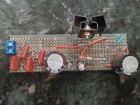
You probably have a solder bridge somewhere, but if I were you I would suggest starting over and see if you can't come up with a better layout. It's kind of a mess tbh you've got jumpers going all over the place, should be avoidable
Before powering up a newly soldered PCB it is a must to verify there are no solder shorts. You have also to investigate whether every node in the actual PCB corresponds to its schematic. So, for instance, if node 1 connects to three components, you have to verify that the three components correspond to what you have on the schematic. This is a tedious process, but it is very important to avoid burning parts unnecessarily.
Last edited:
This circuit is a very simple circuit. Use a bridge rectifier, connect the AC terminals to the transformer's secondary. Connect a smoothing capacitor to the +ve and -ve terminals of the rectifier taking care to connect the smoothing capacitor with its negative terminal with the negative terminal of the rectifier. At this point, you have a simple power supply. You can test if it works at this point but the voltage will be more than what you plan to get. Now, having verified it works, connect the chip regulator with its input to the +ve terminal of the power supply and the adj to the centre point of the voltage divider made of R1 in series with parallelled R2 and R3. Connec the other end of R1 to the out chip terminal and the other ends of R2 and R3 to ground. You can place a small, 10uF, capacitor across the out and ground as a small decoupling capacitor. Please note, a 10uf capacitor is electrolytic and polarity must be respected.
What diodes are you using ? They look like small signal diodes to me.
Yeah they look like OA47 or something of that kind.
Yeah they look like OA47 or something of that kind.
If they are signal diodes then that will be cause of your problem.
Swap them with IN4001s - 1N4007s.
The difference in the last figure is just the voltage rating which is irrelevant in this application.
Or use a bridge rectifier like a W005 or bigger.
Last edited:
Signal diodes generally are low current devices, maybe sub 100mA. The initial charging current on the main cap will take them out.
Signal diodes generally are low current devices, maybe sub 100mA. The initial charging current on the main cap will take them out.
Thanks, everybody. I took it to the bench and upon looking further you all were correct and the 1N4148s I used at the suggestion of a design from another part of the forum were blown out and shorted the board. I appreciate all the replies.
You are kidding, aren´t you? 😕You probably have a solder bridge somewhere, but if I were you I would suggest starting over and see if you can't come up with a better layout. It's kind of a mess tbh you've got jumpers going all over the place, should be avoidable
That is a perfboard, not a PCB, and OF COURSE jumpers are NEEDED since there are no laid out tracks.
Of course jumpers are needed on a perfboard. They're all over the shop is what I'm saying.You are kidding, aren´t you? 😕
That is a perfboard, not a PCB, and OF COURSE jumpers are NEEDED since there are no laid out tracks.
Yeah, I'm in agreement with ubergeeknz.
And I think components should be mounted to the board and not floating on long leads in close proximity to other long leaded components such that a short becomes easily possible. Think about how it is done on a PCB and try to get as close as possible.
I would also use vector board without solder pads.
Yeah, I'm in agreement with ubergeeknz.
And I think components should be mounted to the board and not floating on long leads in close proximity to other long leaded components such that a short becomes easily possible. Think about how it is done on a PCB and try to get as close as possible.
I would also use vector board without solder pads.
Noted and will do, thanks.
I would start again using 1 amp schottky diodes instead of all those small signal diodes and snubbers.
I would start again using 1 amp schottky diodes instead of all those small signal diodes and snubbers.
Will do. What do you suggest for filter capacitors to prevent buzz? I seem to be having that issue with this same PSU design for a 12V supply. I have gotten both to put out the correct voltages with 1N4007 diodes but the same power supply in a 12V configuration has the dreaded 120Hz humming to it.
Will do. What do you suggest for filter capacitors to prevent buzz? I seem to be having that issue with this same PSU design for a 12V supply. I have gotten both to put out the correct voltages with 1N4007 diodes but the same power supply in a 12V configuration has the dreaded 120Hz humming to it.
The Schottky diodes will get rid of the buzz.
If it still hums then smoothing capacitors want increasing.
The Schottky diodes will get rid of the buzz.
If it still hums then smoothing capacitors want increasing.
So just use 4 Schottky diodes in the bridge? Do you have anything I can read up on as to why that would get rid of the buzz?
Thanks!
So just use 4 Schottky diodes in the bridge? Do you have anything I can read up on as to why that would get rid of the buzz?
Thanks!
With normal diodes they can cause switching spikes when they turn on/off.
With normal diodes they can cause switching spikes when they turn on/off.
Ah. That would also prevent me from needing to put small capacitors in parallel with the regular diodes as I have seen others do, correct?
Ah. That would also prevent me from needing to put small capacitors in parallel with the regular diodes as I have seen others do, correct?
Yes.
The switching spikes are usually worst with higher voltages.
I built a valve mixer with normal diodes and the switching spikes were big and could be heard on the audio.
I changed to Schottkies and the buzz went away.
I havent seen switching spikes on low voltages supplies.
- Home
- Amplifiers
- Power Supplies
- Fried My PCB