Hey guys, just wanted to sanity-check that I'm using LTspice correctly.
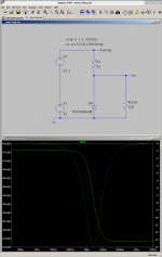
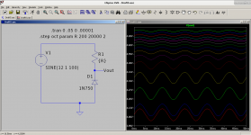
I wanted to see what the frequency response of a basic zener diode shunt regulator looked like (see screenshot 1).
I was surprised that the drop off was only about 4db, then plateaued? This can't be right -- a zener only loses 4db of regulation out to 10GHz?
I looked through the On-Semi "Zener Theory and Design Considerations: https://www.onsemi.com/pub/Collateral/HBD854-D.PDF
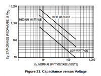
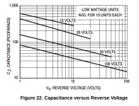
They seem to indicate a simple 1/2 watt low voltage zener's capacitance would be under 1000pF, so I placed a capacitor in parallel and simulated that as well (see screenshot 2). This produced a more expected result -- there is a rolloff which doesn't stop at just 4db.
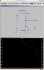
This second simulation seems to indicate a basic shunt regulator should still be in regulation out to 100MHz. Is this realistic?
I wanted to see what the frequency response of a basic zener diode shunt regulator looked like (see screenshot 1).
I was surprised that the drop off was only about 4db, then plateaued? This can't be right -- a zener only loses 4db of regulation out to 10GHz?
I looked through the On-Semi "Zener Theory and Design Considerations: https://www.onsemi.com/pub/Collateral/HBD854-D.PDF
They seem to indicate a simple 1/2 watt low voltage zener's capacitance would be under 1000pF, so I placed a capacitor in parallel and simulated that as well (see screenshot 2). This produced a more expected result -- there is a rolloff which doesn't stop at just 4db.
This second simulation seems to indicate a basic shunt regulator should still be in regulation out to 100MHz. Is this realistic?
Attachments
One thing to be careful of is that parasitics such as capacitance across the diode junction varying with the voltage across it may not be modeled realistically out to such high frequencies. Stray inductances and capacitances elsewhere in the circuit will affect what you get in real life at those frequencies as well, and the model won't show that unless you can include them in it.
As egellings indicates, you need to search around and read through various articles and research papers that go through the process of identifying, measuring, simulating and comparing results for high frequency operation of simple circuits. I could imagine there would be quite a few on-line using google search and LTSpice.
To begin with, you ar feeding it throughb meager 82 ohm resistance.
To boot, equivalent capacitance will be shunted by zener diode internal impedance, which by definition is VERY low.
Or it wouldn´t be a voltage regulator/stabilizer.
Combine both and I can see capacitance being a minuscule factor.
Also capacitance is not the same when not "zeneing" (no avalanche reached so it´s basically "a regular diode") than when it is.
The max Rz is 15 ohms, and the 82 ohms with the 150 ohms load represent an equivalent source R of about 50 ohms. So the best you can expect is 15/50 is about 10dB suppression.
The max 15 ohms is in the data sheet, who knows what's in the spice model. You could check that.
Replace the 82 ohms with a current source and Bob's your uncle.
Also that 150 ohms needs to go or to be increased a lot. Why is it there?
Jan
The max 15 ohms is in the data sheet, who knows what's in the spice model. You could check that.
Replace the 82 ohms with a current source and Bob's your uncle.
Also that 150 ohms needs to go or to be increased a lot. Why is it there?
Jan
Also that 150 ohms needs to go or to be increased a lot. Why is it there?
150 just represents the load. Why would that need to go or be increased?
Well if that is the load it obviously cannot go. But it also means that the series R cannot be very large so that limits the effectiveness of the zener.
Two possible options are an emitter follower between the zener and the load, or replace the series R with a current source.
Is the supply 12V constant or does it have ripple? Is the load constant?
jan
Two possible options are an emitter follower between the zener and the load, or replace the series R with a current source.
Is the supply 12V constant or does it have ripple? Is the load constant?
jan
Well, you should have said so.150 just represents the load. Why would that need to go or be increased?
To me (and maybe to ohers ) it´s just a voltage divider which could be there to reduce Zener dissipation, go figure.
Well if that is the load it obviously cannot go. But it also means that the series R cannot be very large so that limits the effectiveness of the zener.
Two possible options are an emitter follower between the zener and the load, or replace the series R with a current source.
Is the supply 12V constant or does it have ripple? Is the load constant?
jan
thanks jan, yes the 12V supply will have ripple (the sine is just a stand-in to represent rectified + filtered but unregulated voltage source).
I'm not sure I understand -- are you saying that it is desireable to increase the series resistor, i.e. doing so would increase regulation? I thought the opposite was true?
The regulation depends on the ratio of series R to zener R, so is largest if the series R is largest with a given zener. Hence the suggestion for a current source in stead of the series R.
For example, with 1V ripple, a series R of 1k and zener R of 10 ohms, the suppression is ~1000/10 = 100 so the ripple on the zener (and load) will be 10mV.
It is really a standard resistive divider but only for AC.
Jan
For example, with 1V ripple, a series R of 1k and zener R of 10 ohms, the suppression is ~1000/10 = 100 so the ripple on the zener (and load) will be 10mV.
It is really a standard resistive divider but only for AC.
Jan
Thanks jan, when you say "series R" and "zener R", which refers to which? Is "zener R" the series current-limiting resistor ("Rz" in post #1), or does "zener R" refer to the dynamic impedance of the zener?
Here is a simulation which seems to indicate that higher zener current is what improves regulation (see screenshot, lower resistance values are near the top of the graph).
Here is a simulation which seems to indicate that higher zener current is what improves regulation (see screenshot, lower resistance values are near the top of the graph).
Attachments
I recall a software package called Eagleware that was specifically made to model high frequency circuits.
Keysight bought that years ago, now it is known as PathWave.
PathWave Design Software | Keysight
PathWave Design Software | Keysight
Last edited:
- Home
- Design & Build
- Software Tools
- Frequency response of zener shunt regulator