Hi,
I am trying to simulate The Williamson Amplifier in LTspice which is in the attachment.
This is the frequency response created by using Spice commands:
.measure tmp max mag(V(load))
.measure BW trig mag(V(load))=tmp/sqrt(2) rise=1 targ mag(V(load))=tmp/sqrt(2) fall=last
It looks almost the same as in the articles by the inventors of circuit and flat between 2Hz and 18KHz.
And, this is the transient analysis output at 10Hz., 1kHz., 10kHz. and 14kHz.
Since the BW between 2Hz and 18KHz is "flat", i was expecting same power outputs for any input frequency between the two. But it is not.
What could be possible reason for this discrepancy?
I am new to LTSpice so, maybe, i am doing something wrong.
Thanks for replies in advance.
I am trying to simulate The Williamson Amplifier in LTspice which is in the attachment.
This is the frequency response created by using Spice commands:
.measure tmp max mag(V(load))
.measure BW trig mag(V(load))=tmp/sqrt(2) rise=1 targ mag(V(load))=tmp/sqrt(2) fall=last
An externally hosted image should be here but it was not working when we last tested it.
It looks almost the same as in the articles by the inventors of circuit and flat between 2Hz and 18KHz.
And, this is the transient analysis output at 10Hz., 1kHz., 10kHz. and 14kHz.
An externally hosted image should be here but it was not working when we last tested it.
Since the BW between 2Hz and 18KHz is "flat", i was expecting same power outputs for any input frequency between the two. But it is not.
What could be possible reason for this discrepancy?
I am new to LTSpice so, maybe, i am doing something wrong.
Thanks for replies in advance.
Attachments
Could you also post the circuit diagram of your model (williamson1.asc) in pdf-format (or at .gif etc.).
I do not have all the components you have used, but that can be solved if the schematic would available.
I got this error message while opening your .asc:
I do not have all the components you have used, but that can be solved if the schematic would available.
I got this error message while opening your .asc:
Attachments
One has to do the closed Loop transient analysis at 1Hz square wave at very low level, 1/2W or less at the output;, no more as o/p tranny will saturate. What one is doing is to assess the closed loop droop, as if the interstage coupling capacitors are too high value (as per original Williamson) the circuit gain with the output transformer in circuit is on the cusp of being in LF oscillation. The cure is to reduce the interstage capacitor values from the phasesplitter outputs. I am not sure SPICE can simulate this, try by reducing the values and the frequency and see what happens.
I have the development analogue stuff on another stick and will have to dig it out.
The secret to to examine the very low frequency "Q" of the waveform on the output as it has time to settle from one cycle,. hence a high persistent scope of storage scope is vital to view the full details. I always aim for a Q of about 1, this culminates a three/four stage Williamson with generalised 25dB global nfb, then running into oscillation when the global feedback components are decreased, i.e another 10dB will create instability.
This may appear mighty technical to many but I am quite sure once this is mastered, nirvana in building amps for stability is obtained. Then the emphasis is the upper end, but I tend to avoid describing that as the unpredictability of layout can be quite a nuisance.
Hope this helps.
richy
I can open .asc but the output valves were missing.
(You need to post a complete file and include all the models needed so that it will run on any standard LT install)
(You need to post a complete file and include all the models needed so that it will run on any standard LT install)
One has to do the closed Loop transient analysis at 1Hz square wave at very low level, 1/2W or less at the output;, no more as o/p tranny will saturate. What one is doing is to assess the closed loop droop, as if the interstage coupling capacitors are too high value (as per original Williamson) the circuit gain with the output transformer in circuit is on the cusp of being in LF oscillation. The cure is to reduce the interstage capacitor values from the phasesplitter outputs. I am not sure SPICE can simulate this, try by reducing the values and the frequency and see what happens.
I have the development analogue stuff on another stick and will have to dig it out.
The secret to to examine the very low frequency "Q" of the waveform on the output as it has time to settle from one cycle,. hence a high persistent scope of storage scope is vital to view the full details. I always aim for a Q of about 1, this culminates a three/four stage Williamson with generalised 25dB global nfb, then running into oscillation when the global feedback components are decreased, i.e another 10dB will create instability.
This may appear mighty technical to many but I am quite sure once this is mastered, nirvana in building amps for stability is obtained. Then the emphasis is the upper end, but I tend to avoid describing that as the unpredictability of layout can be quite a nuisance.
Hope this helps.
richy
Yes, it helped.
After i reduced input amplitude down to 0.1V, it worked as it should have.
I was thinking that since AC analysis use 1V as input, it is also the optimal level for the transient simulation which is apperantly wrong.
Thank you very much.
Last edited:
I just got your circuit simulated. Yes, the output tubes were driven to the grid current, i.e. heavily overloaded.
With the transient analysis you are able to analyse the linearity/distortion with different output power levels.
Therefore it is essential to adjust the input level very carefully and allways be aware about the signal level you are using.
With the transient analysis you are able to analyse the linearity/distortion with different output power levels.
Therefore it is essential to adjust the input level very carefully and allways be aware about the signal level you are using.
It is still a bit strange.
The level shown in the first post is only 15-20W, and the lower frequencies visible do not show signs of heavy clipping, and +/- signals are nicely symmetrical.
Also a little strange is that the output power is highest at lower frequencies;
20W at 10Hz, decreasing to about 12W at 14Khz.
SB
The level shown in the first post is only 15-20W, and the lower frequencies visible do not show signs of heavy clipping, and +/- signals are nicely symmetrical.
Also a little strange is that the output power is highest at lower frequencies;
20W at 10Hz, decreasing to about 12W at 14Khz.
SB
nec3
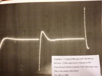
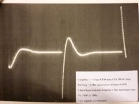
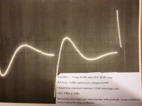
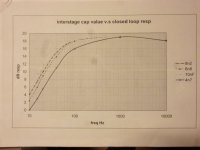
Here are some quite old pics of the work I did in 1965 and the open loop vs cap values more recent. Note these are for the 3 stage 1955 KT88-50 amp which was an excellent performer despite using a self balancing paraphase inverter.
When interpreting these pics, note the THD decreases as the interstage cap value is increased but the transient Q also worsens. It makes sense as "the payoff" of the optimum damping has to be increased distortion, as the value of the interstage cap pertains to the amount of closed loop feedback handled at the LF end.
Each and every designed amp will exhibit these features.
The optimum findings also coincide with Steinmetz's law; that with the standard iron used at that time, the 1.4% F2 thd is the figure obtained at the cutoff frequency and excitation design frequency of the transformer...the result that many output transformers produced of that era, and even now.
It will become obvious to seasoned designers that amplifiers exhibiting a good closed loop response will behave and settle better on fast rising signal transients, sound better and less muddled..
Big cap values certainly don't imply good bass response ! Conversely, too small value interstage caps certainly will sound thinner.
richy
Attachments
nec3
Here are some quite old pics of the work I did in 1965 and the open loop vs cap values more recent. Note these are for the 3 stage 1955 KT88-50 amp which was an excellent performer despite using a self balancing paraphase inverter.
When interpreting these pics, note the THD decreases as the interstage cap value is increased but the transient Q also worsens. It makes sense as "the payoff" of the optimum damping has to be increased distortion, as the value of the interstage cap pertains to the amount of closed loop feedback handled at the LF end.
Each and every designed amp will exhibit these features.
The optimum findings also coincide with Steinmetz's law; that with the standard iron used at that time, the 1.4% F2 thd is the figure obtained at the cutoff frequency and excitation design frequency of the transformer...the result that many output transformers produced of that era, and even now.
It will become obvious to seasoned designers that amplifiers exhibiting a good closed loop response will behave and settle better on fast rising signal transients, sound better and less muddled..
Big cap values certainly don't imply good bass response ! Conversely, too small value interstage caps certainly will sound thinner.
richy
Mr. Richy,
The circuit i try to simulate is in fact a modified version of the original by Talbot M. Wright and published by Electronics World in 1961. (1)
He reduced the interstage capacitance from 250nF to 220nF. The first value could also be chosen wrongly. I will try to re-calculate it using the formulas given at (2)
The coupling cap in the very first version of Williamson (3) is unsurprisingly in accordance with your suggestions. Of course it has correlation with the resistors. I will know it after i finish calculations.
On the other hand, while i am able to measure THD and BW with the help of LTSpice, I do not know how to measure (yet) the damping factor and transient "Q" unfortunately. I will have to read more about these two.
Thank you once again for your reply.
Regards,
Necati
1. Williamson amplifier
2. http://diyaudioprojects.com/Technical/Papers/Design-of-an-Audio-Frequency-Vacuum-Tube-Amplifier-Brad-Bryant-2000.pdf
3. The Williamson Amplifier
The KT88-50 paraphase circuit operates at higher impedances when compared to true Williamson with buffer driver. For those who wish to replicate what I've done, must take into account all R/C time constants around the relevant circuits otherwise one will get nowhere.
Your difference between 220nF to 250nF isn't much. I did all my work with ratio min twice between values. To get results I would have started with at least half, i.e 100nF.
First, I do the open loop response (without gnfb) and must be plotted. For others starting out with the physics of closed loop design must realise that when global nfb is connected, the circuit will correct the response to a flat one but the value of the interstage caps and relevant resistors will determine when the loop gain runs out.
I'd be very surprised if SPICE can simulate and determine core distortion, as one would also have to enter core material and all parameters.
richy
- Status
- Not open for further replies.
- Home
- Amplifiers
- Tubes / Valves
- Frequency Response of Williamson Amplifier in LTspice