R11 can't have 17 VDC on both sides and still be passing 85mA. Something is not as you think it is.
All good fortune,
Chris
All good fortune,
Chris
So, not much decoupling. The whole scheme is sketchy, but Stephie likes the unusual for its own sake.
All good fortune,
Chris
All good fortune,
Chris
Steve Bench tried many unique circuits, this is one of the best examples. 👍That is not my schematic. It is Stevie Bench's. In the link that I provided, he describes the amplifie
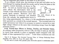
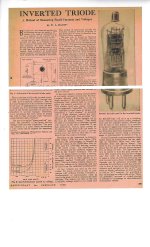
It is based on the real inverted triode describe by Terman in 1928. At that time it was a convenient
way to measure HV which was applied to the plate of a specially built triode.
The Plate lead was brought out to top cap.
Attachments

I think that inverted triodes are a great way of driving low-impedance headphones. I have built many versions of a headphone amplifier with a pair of Lundahl LL2765 output transformers. It sounds fine, but the inverted triode amplifier sounds even better and can be built at a much lower cost. I use a pair of $15 chokes. The chokes in the driving stage can be omitted if the voltage of the anode supply is increased.
Nothing will.happen in that circuit.
700ma capable less then 1 ma flowing. 7 and 14v are just way to low for any current flow.
At much higher voltage 6A3 summer is correct meltdown will happen.
700ma capable less then 1 ma flowing. 7 and 14v are just way to low for any current flow.
At much higher voltage 6A3 summer is correct meltdown will happen.
Go to the Steve Bench link & click on 5687 Inverted Curves. The forward voltage is quite low at a realistic current.At much higher voltage 6A3 summer is correct meltdown will happen.
Many tubes in parallel as Steve has shown us, a significant output is possible. 👍
http://diyaudioprojects.com/mirror/members.aol.com/sbench101/
- Home
- Amplifiers
- Tubes / Valves
- Frequency Response in LC circuit