I need IC on 12V to drive two bipolar transistors in push-pull on 50-100kHz with ferrit transformer?
I don't want full smps with feedbacks functionality...something more simple just to drive transistors. Also need schematic? Is it possible to accomplish this with simple 555?
I don't want full smps with feedbacks functionality...something more simple just to drive transistors. Also need schematic? Is it possible to accomplish this with simple 555?
Do you need a sine wave or square wave (switching) output?
What power levels are you attempting to drive, in your push-pull pair?
What power levels are you attempting to drive, in your push-pull pair?
Check the link. Intersil Corporation
Hope this solves your need
I mean this IC as a building base. you can connect this to any wide band power amplifier.
Hope this solves your need
I mean this IC as a building base. you can connect this to any wide band power amplifier.
Last edited:
I don't have +/- 10V voltage. I have 12V only. Also don't need sine or triangle waves.
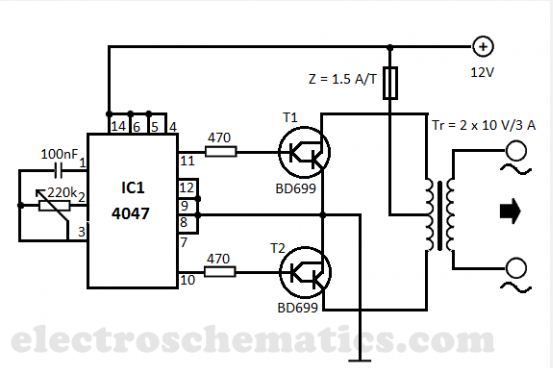
Something like this,just not 50Hz,but 50-100kHz.
Something like this,just not 50Hz,but 50-100kHz.
A problem with such a simple circuit is device conduction overlap or cross conduction as the output devices do not turn off abruptly. In other words both transistors will be on together for a significant time leading to large losses and heat generation. You really need some form of dead zone where both devices are off but that involves extra logic unless you research some off the shelf SMPS drivers.
To design something like this properly is quite a job... however if you are just experimenting then by all means try something like you have shown.
I wonder whether FET's would work better as switching devices due to the low current drive available from the CMOS oscillator.
Something like this for a full design maybe,
http://www.fairchildsemi.com/ds/KA/KA3525A.pdf
I wonder whether FET's would work better as switching devices due to the low current drive available from the CMOS oscillator.
Something like this for a full design maybe,
http://www.fairchildsemi.com/ds/KA/KA3525A.pdf
is this the simplest it can be?
An externally hosted image should be here but it was not working when we last tested it.
Here is a circuit like that: 12V DC to 220V 100W Inverter with 4047 IC & IRF540I wonder whether FET's would work better as switching devices due to the low current drive available from the CMOS oscillator.
Last edited:
is this the simplest it can be?
Take a look at Rod Elliot`s site, his version is even more simple:
Switchmode Power Supply For Car Audio
modern sw ps chips can drive the power switches directly
but if your goal is a 12 V supply ~50 W power audio amp you could make a 12 V audio power amp drive a step up audio output transformer - small turns ratio, low impedance make a SS aduio output xfmr easier to design than tube amp output xfmr
but if your goal is a 12 V supply ~50 W power audio amp you could make a 12 V audio power amp drive a step up audio output transformer - small turns ratio, low impedance make a SS aduio output xfmr easier to design than tube amp output xfmr
is this the simplest it can be?
An externally hosted image should be here but it was not working when we last tested it.
Since the 3524 is referenced to ground, Q2 and Q4 will do nothing, since the outputs can not swing below ground to turn them on.
paul
Since the 3524 is referenced to ground, Q2 and Q4 will do nothing, since the outputs can not swing below ground to turn them on.
paul
Don't follow 🙂
Each NPN/PNP pair form a simple power buffer stage. If the base of the PNP is driven low it will active remove or pull down the FET gate voltage giving a rapid turn off.
The PNP turns on when the base volts drops below the emitter...
Hi guys,
what is over shoot? And why not switch d fets directly.
Overshoot usually means when a signal doesn't settle to its nominal value put "overshoots" and then returns.
It can apply to small signal design using opamps that are incorrectly compensated or in SMPS as here where ringing and inductive artifacts come into play.
I wondered why the FET's couldn't be switched directly too... the IC has a 500ma drive capability. Perhaps the peak current exceeds this if the IC can switch with very fast rise/fall times as it charges/discharges the FET gate capacitance.
Mooly, it is strange to me that you need 0.5A to drive 2 mosfets?
Isn't mosfet G-S resistance in MegaOhms? So voltage (about 7V for saturation) opens them. Not current. Why would you want ampers for driving them?
Isn't mosfet G-S resistance in MegaOhms? So voltage (about 7V for saturation) opens them. Not current. Why would you want ampers for driving them?
Mooly, it is strange to me that you need 0.5A to drive 2 mosfets?
Isn't mosfet G-S resistance in MegaOhms? So voltage (about 7V for saturation) opens them. Not current. Why would you want ampers for driving them?
The G-S resistance is even higher than that 🙂 However that only applies at DC. That "resistance" is in parallel with the G-S capacitance and it's driving that capacitance that requires the current. If it were only 4nF then that gives an "equivalent" resistance of only 400 ohms at 100khz. To drive that cleanly at say 10 volts requires the high current capability in order to get fast rise and fall times.
- Status
- Not open for further replies.
- Home
- Amplifiers
- Power Supplies
- Frequency generator 50-100kHz IC?