Hi All
just a quick question, on the following schematic, If I were to add switches to the input of each of the 3 frequecy responses after the resistor and before the Pots, would this act as a Kill switch for each selected level (Bass, mid + Treble) ??
Would I need to add any other circuits??
thanks
Chris
just a quick question, on the following schematic, If I were to add switches to the input of each of the 3 frequecy responses after the resistor and before the Pots, would this act as a Kill switch for each selected level (Bass, mid + Treble) ??
Would I need to add any other circuits??
thanks
Chris
Attachments
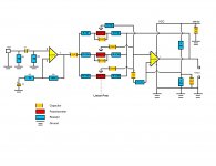
No. That appears to be a 3-way version of the Baxandall active tone control. It can't cut out any frequency range, but just boost or reduce.
No. That appears to be a 3-way version of the Baxandall active tone control. It can't cut out any frequency range, but just boost or reduce.
I interpreted it as disabling the control function of the pot, not changing the audio response. I don't think it would work that way but it wouldn't hurt to try.
G²
Where do bad seeds come from?
R1, 2 should not go to ground, but to the junction of R3/C2 and than to the junction of pin 5 of the IC. Than the 1uF after pin1 of the IC can be eliminated. And all of that is not optimal.
To go back to your query: A swithc after the pot should be sufficient. E
R1, 2 should not go to ground, but to the junction of R3/C2 and than to the junction of pin 5 of the IC. Than the 1uF after pin1 of the IC can be eliminated. And all of that is not optimal.
To go back to your query: A swithc after the pot should be sufficient. E
R1 should still go to ground, but you are right about R2 - it should go to the reference point for the second opamp.
A switch 'after' the pot (presumably after the wiper) would not cut a band, but merely render it uncontrollable so it would pick up the tails of whatever was set by the adjacent bands. For the top (bass) pot there is the complication that this also provides DC bias so the switch would need to be bypassed by a high value resistor. Arrangements would have to be made to avoid switching clicks.
Much better to start with a circuit designed to allow cutting each band independently.
No. You have no bias supply for the first opamp. Also, the CR across the + and - inputs for the second opamp should not be there. Why don't you use normal symbols - the colour coding is confusing.
As I said, I suggest you find an existing circuit which does what you want. You need to learn more before trying to design your own.
As I said, I suggest you find an existing circuit which does what you want. You need to learn more before trying to design your own.
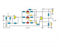
lol... funny thing is, this was an existing design,,, I didnt have a CAD program so had to use Excel for the time being however,
I now have a CAD design program, hopefully this will assist,, I will try to upload as soon as Ive implemented the design..
as for the Bias (??) I thought the LM358 only had on VCC and Ground, hense this is shown on the 2nd (1B) opamp.
really appreciate your patience..
Chris
I now have a CAD design program, hopefully this will assist,, I will try to upload as soon as Ive implemented the design..
as for the Bias (??) I thought the LM358 only had on VCC and Ground, hense this is shown on the 2nd (1B) opamp.
really appreciate your patience..
Chris
The bias for both op-amps appears to come from the two 10K resistors on the right hand side. They form a voltage divider giving Vcc/2 at their junction.
Do you want to cut each frequency range or defeat each tone control?
For defeating the mid and treble controls, you could just disconnect (that is, insert a switch in series) the pots center lead. For the bass, try shorting (that is, connecting a switch between leads 1 and 3) the pot (this may affect the other bands, I dunno).
Emerson Prado
For defeating the mid and treble controls, you could just disconnect (that is, insert a switch in series) the pots center lead. For the bass, try shorting (that is, connecting a switch between leads 1 and 3) the pot (this may affect the other bands, I dunno).
Emerson Prado
Redirection of thread (circuit design)
http://www.diyaudio.com/forums/analog-line-level/204325-all-one-mixer-pc-project.html
Hi there,, just to endure Im posting in the correct thread so as not to lose focus.. lol thanks
Chris
No. You have no bias supply for the first opamp. Also, the CR across the + and - inputs for the second opamp should not be there. Why don't you use normal symbols - the colour coding is confusing.
As I said, I suggest you find an existing circuit which does what you want. You need to learn more before trying to design your own.
http://www.diyaudio.com/forums/analog-line-level/204325-all-one-mixer-pc-project.html
Hi there,, just to endure Im posting in the correct thread so as not to lose focus.. lol thanks
Chris
- Status
- Not open for further replies.
- Home
- Source & Line
- Analog Line Level
- Frequency cut out switches. Graphic EQ.