Hello friends!
Time has come to use Eminence Lab 12 that has been laying around for some time. I decided to build a Tapered Transmission Line enclosure for the purpose of sub bass application 20-100Hz. The drivers were blown and have been fitted new coils on kapton base. I measured the TS parameters and did the simulations on both Hornresp and Lenard Audio TL and got good results


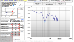
but this is the reality when measuring the freq response - a large dip at 55hz, so - out of phase in box?

this is the actual project, the sub is on the bottom.
August
Time has come to use Eminence Lab 12 that has been laying around for some time. I decided to build a Tapered Transmission Line enclosure for the purpose of sub bass application 20-100Hz. The drivers were blown and have been fitted new coils on kapton base. I measured the TS parameters and did the simulations on both Hornresp and Lenard Audio TL and got good results
An externally hosted image should be here but it was not working when we last tested it.
but this is the reality when measuring the freq response - a large dip at 55hz, so - out of phase in box?
this is the actual project, the sub is on the bottom.
An externally hosted image should be here but it was not working when we last tested it.
August
Last edited:
Chances are it's room related. Changing the location of the sub within the room is likely to give you a new set of peaks and dips to work with.
Chris
Chris

this measurement was taken outside
The low end is not smooth as it should be.
I am completely out of ideas
Last edited:
It' s 151cm. Why do you ask? I have taken measurements upside down, with the port on the ground, they are more or less the same.
A number of things:
1. The t/s parameters of the LAB12 that you're using don't match the published t/s parameters
2. The Hornresp sim assumes that the vent and the driver (basically all output from the sim are located close together and producing output from the same plane. Your build has the driver and the vent at a considerable distance apart.
3. The build does not match the sim (cross-sectional area and path length)
A number of things:
1. The t/s parameters of the LAB12 that you're using don't match the published t/s parameters
2. The Hornresp sim assumes that the vent and the driver (basically all output from the sim are located close together and producing output from the same plane. Your build has the driver and the vent at a considerable distance apart.
3. The build does not match the sim (cross-sectional area and path length)
1. The drivers were blown and have been refitted with new kapton coils. The parameters were remeasured using DATS2
2. The hornresp sim shows that the driver and the vent are 182cm apart.
3. The build is almost spot on to my understanding. even if I simulate a few cm off for cross sectional area the simulation stays almost the same and nowhere near the actual measurement.
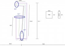
Here is the drawing with all the measurements

Here is the drawing with all the measurements
That enclosure height is around the same at 1/4W at 55Hz.
I don't think that is a coincidence. You might be experiencing cancellation at 55Hz due to internal reflection being out of phase with the driver at the driver's position.
That enclosure height is around the same at 1/4W at 55Hz.
I don't think that is a coincidence. You might be experiencing cancellation at 55Hz due to internal reflection being out of phase with the driver at the driver's position.
That I had not taken into consideration.
I previously routered a hole towards the beginning of the transmission line, and put the driver there, the measurement was still off.
But there could be a standing wave. So that means that the box should not be folded longer than 0,86m (1/4wl of 100Hz)? If the goal is 25-100Hz
I read I could use mineral wool for these problems? Put it on the walls
I have long fiber lambs wool at hand, I bought it for dampening fullrange transmission line enclosures.
Could the massive magnet structure of this driver be constricting the line at the bottom of the box?
Could the massive magnet structure of this driver be constricting the line at the bottom of the box?
the driver sits in the box like this

plus the magnet is not 28cm wide in diameter.
And again - I did put the driver on the start of the line with no noticeable changes.
I think its a standing wave like Steele said. I will experiment with this later and update the thread.
Thanks everybody
....But there could be a standing wave....
No!
So that means that the box should not be folded longer than 0,86m (1/4wl of 100Hz)? If the goal is 25-100Hz
No!
I read I could use mineral wool for these problems?
No
Put it on the walls
Check the amount needed using HR.
I have long fiber lambs wool at hand,....
IME: The very best to use when damping a TL
b🙂
Attachments
So an air column 1.5 meters long open at both ends cannot resonate? Or is the term standing wave problematic?
The OP mentioned that the measurements were taken outside, so room effects should not have impacted the measured FR.
25hz are also not quite there and it resonates massively at 40ish. My guess is that for some reason 50hz is out of phase and that causes a reaction that affects other frequencies. I will try stuffing it with lambs wool and take some more measurements. Btw there is another tl speaker standing in my room and it sounds totally fine and amazing.

Using audiophile-grade pillow stuffing, here're my data (including THD):
17-foot labyrinth
Long pipe to sequester rear wave
B.
17-foot labyrinth
Long pipe to sequester rear wave
B.
Last edited:
Why is the driver at the bottom of the box? Most transmission lines I have seen the line start with the driver. I have one (not my design) with a front facing 25cm (10") driver and the line folds upwards and to the front (I grabbed an image from the interwebs)
An externally hosted image should be here but it was not working when we last tested it.
perhaps for stable?Why is the driver at the bottom of the box?
a question not directly at the OP, did I label it correctly?
Attachments
perhaps for stable?
a question not directly at the OP, did I label it correctly?
Yes you labelled it correctly.
Driver is at the bottom for two reasons - one of them is also an answer to gfx1 question - because for this design with the specific driver towards the middle of the TL it gave a completely flat freq response so no stuffing was needed thus reaching the maximum output and simplicity.
The other reason was that I wanted the subwoofer to be invisible, and the construction was going to have an 8" kickbass-midrange speaker where the space is below the port. This design approach naturally made me put the woofer at the bottom.
- Status
- Not open for further replies.
- Home
- Loudspeakers
- Subwoofers
- Freq dip at 55 Hz Tapered TL