Help with jhl2005
Hi
Any one know where I can find some info on the jhl 2005 amp.
I buid them allmost 4 years ago and of cause lost all the "paperworks"
Adjustment procedure would be most welcome and maybe a scematic .
I have one pair built and they where actually adjusted and testet.
Sounded real class a but to weak for my speakers at the time.
Power transistors was then reused for a bigger amp.
So I need to adjust for new power transistors.
I allmost sure I found the info here and printed it out for my "book of builds" but cant find it.
Right now im completing a tri-amp system,3 way active inline filter and I think this little amp will be fine for the highs.
I have everything needed;
PSU,Cap multipliers,enclosure,connecters,heatsinks.
It seems like siliconray´s site is gone. (R.I.P) .No help there.
Hope someone here can inlighten my old dusty memory.
Jan
PS.I got 2 pairs of pcbs.
1 pair free for best answer.
The other pair,well try to PM
No free shipping
Hi
Thanks Tony
Another piece in the puzzle in place.
Thats exactly what I need.🙂
Your notes on adjustment are clear and concise.
Just one question:Output,open or with load under adjustment ?
If you want a free pair of pcbs,send a PM
Jan
Thanks Tony
Another piece in the puzzle in place.
Thats exactly what I need.🙂
Your notes on adjustment are clear and concise.
Just one question:Output,open or with load under adjustment ?
If you want a free pair of pcbs,send a PM
Jan
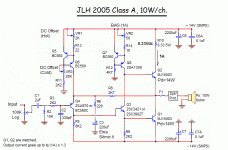
This will answer all your questions...see attached file and text below.
VR1,2 and VR3 adjustment
1. VR2 = Bias... - Set to 330mv across R10 330mOhm ( Equals 1A Bias Current... )
2. Power the amp to Full Heat ( app. one hour of operation ), and udjust VR1 to 0.00 Volt DC Across the output terminals ( With input shorted / No load )
3. Turn off the Amp, and allow to cool off. Re-adjust in cold state DC Offset to almost 0.00 with VR3.
4. Wait for full heat, and repeat adjustment of VR1 , VR3 until you're satisfied with the difference in cold and hot state. It should be possible to obtain app. +/- 30 mV DC offset - Which is quite OK. ...I have 16mV and 20mV.
BR,
Eric
Attachments
Hi
Thanks Eric.
Its all clear to me now.Im recalling the procedure.
If you want a free pair of pcbs,send a PM
Jan
Thanks Eric.
Its all clear to me now.Im recalling the procedure.
If you want a free pair of pcbs,send a PM
Jan
Hi Jan,
Basically as per what Eric said above, Input shorted, no load output.
As per the notes on the schematic, I'm running at around 580mV across R10 (0.33 ohms) giving about 1.9 Amp bias current. Supply voltage is around ± 20V.
Runs at about 40°C above ambient with the heat sinks used.
More info of the build on pages 29 and 30 of this thread under my name.
Cheers
Thanks for the offer of the PCB's Eric but no real use for them at this time. I'm sure they will go to a worthy enthusiast - or you'll find you need them at a later stage.
BTW Jan, the drivers get very hot which is why I kept the quiescent current down to a little less than 2 amps. There's little room for any heat sinking either so I used LED heat sinks on the drivers. Also upgraded R10 to a higher wattage for the same reason.
Hi
This is embarrasing,I just found out I actually posted in this tread some years ago.
My memory is failing me,sigh
Any way thanks for your help.
Jan
This is embarrasing,I just found out I actually posted in this tread some years ago.
My memory is failing me,sigh
Any way thanks for your help.
Jan
Hi Jan
We are all some how getting older...lol
Would you happen to have the headphone pcb ?
If not, I guess the power amp could be used as a HA with some changes
BR
Eric
We are all some how getting older...lol
Would you happen to have the headphone pcb ?
If not, I guess the power amp could be used as a HA with some changes
BR
Eric
Hi
Any one know where I can find some info on the jhl 2005 amp.
I buid them allmost 4 years ago and of cause lost all the "paperworks"
Adjustment procedure would be most welcome and maybe a scematic .
I have one pair built and they where actually adjusted and testet.
Sounded real class a but to weak for my speakers at the time.
Power transistors was then reused for a bigger amp.
So I need to adjust for new power transistors.
I allmost sure I found the info here and printed it out for my "book of builds" but cant find it.
Right now im completing a tri-amp system,3 way active inline filter and I think this little amp will be fine for the highs.
I have everything needed;
PSU,Cap multipliers,enclosure,connecters,heatsinks.
It seems like siliconray´s site is gone. (R.I.P) .No help there.
Hope someone here can inlighten my old dusty memory.
Jan
PS.I got 2 pairs of pcbs.
1 pair free for best answer.
The other pair,well try to PM
No free shipping
In case you want more info on the amp, try this link:
The Class-A Amplifier Site
Regards,
I built one of these amps using the Siliconray boards some years ago which hasn't been used. I recently ran it for a few days and had problems with the L channel blowing the pcb fuse. Having checked it over it seems that I can't now get the dc offset down and my light bulb tester is glowing brightly when the L channel only is connected (dual mono double psu design)
I Built the board using TIP3055 transistors. My electronics knowledge has increased a little since I built that amp and I have a few questions I wonder if anyone can answer.
I used the TIP 3055's in both positions on the board, but now wonder whether they should both be the same or whether one of them should have been a P channel 2955. I am probably going to replace all the output transistors on both boards and wondered which ones would be favourite for the board's interpretation of the JLH amp.
this pattern has never been stable.
I tried several things but nothing worked, it swayed, I gave up.
I tried several things but nothing worked, it swayed, I gave up.
I had forgotten about the above post. The amp has not been fixed. Anyone?
I have these boards, still unfinished, in a drawer...
I've attached zip file with board and schematic images. If I recall correctly there are several posts earlier in this thread that purport to describe the set-up process.
I did finish the SiliconRay headphone version and it worked well and sounded good.
Attachments
Why not use the original, proven by many.
https://www.diyaudio.com/forums/sol...-mosss-jlh-2005-design-files.html#post6572301
Patrick
https://www.diyaudio.com/forums/sol...-mosss-jlh-2005-design-files.html#post6572301
Patrick
And here the original Gerber data from Geoff Moss :
https://www.diyaudio.com/forums/sol...-mosss-jlh-2005-design-files.html#post6570824
Patrick
https://www.diyaudio.com/forums/sol...-mosss-jlh-2005-design-files.html#post6570824
Patrick
I had forgotten about the above post. The amp has not been fixed. Anyone?
Just saw this post this am.
The output transistors were specified as both being MJ15003 (NPN).
The trick (from memory) is to set both pots mid way and then adjust for quiescent current followed by output voltage (to 0V).
Repeat adjustments until the quiescent current and output voltage are stable (probably 3 to 5 times) making sure the heatsink(s) temperature is stable (at 'operating temperature') each time.
Have no issues with the amps per se. Sound is very good.
The problem is some 50Hz 'hum' in my setup which arises from the power supply I used. One really needs a lot of capacitance or something like a ripple eater to maintain a steady current to these amps with minimal ripple. Mine is 2 separate power supplies with 20,000 uF per channel (without opening the case). I think 47,000 uF per channel in a standard configuration PSU would probably be a minimum (untested).
HTH
I had forgotten about the above post. The amp has not been fixed. Anyone?
Found this PDF file I'd made which provides schematic and adjustments in my handwriting.
Hope you can read it. 😱
Attachments
- Home
- More Vendors...
- Siliconray Online Electronics Store
- ★★ Free PCB for JLH 2005 Class-A Amplifier