I think you should check the resistance of each inductor.
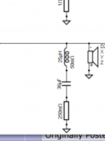
(BTW, the 10m resistor in the tweeter was meant to be deleted.)
(BTW, the 10m resistor in the tweeter was meant to be deleted.)
Now i notice that the graph ended like yours,the resistance on the coils was wrong,so i must test this setup.
But will the reciewer like 3 ohms? Just wondering?
If it just is a little peak on 3ohm is it not that bad?
Now new crossover parts Will be ordered.
This is gonna be interesting 🙂
But will the reciewer like 3 ohms? Just wondering?
If it just is a little peak on 3ohm is it not that bad?
Now new crossover parts Will be ordered.
This is gonna be interesting 🙂
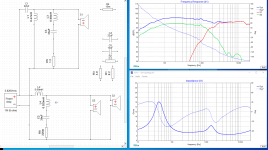
I should just say that it would cause no problems for me or my amps, but I'm not prepared to speak for every amp out there. I was getting 3.5 ohms, just at that one higher frequency. I guess my sim was automatically applying fifteenth octave smoothing if that makes a difference. Anyway, I would expect a dip like this with a 4 ohm driver, and it is normal to see 6 ohm (or less) regions in a nominal 8 ohm setup.
The component that made the most difference here was the first tweeter inductor, then the first capacitor. If you play with the values, you'll see 😉.
The component that made the most difference here was the first tweeter inductor, then the first capacitor. If you play with the values, you'll see 😉.
I should just say that it would cause no problems for me or my amps, but I'm not prepared to speak for every amp out there. I was getting 3.5 ohms, just at that one higher frequency. I guess my sim was automatically applying fifteenth octave smoothing if that makes a difference. Anyway, I would expect a dip like this with a 4 ohm driver, and it is normal to see 6 ohm (or less) regions in a nominal 8 ohm setup.
The component that made the most difference here was the first tweeter inductor, then the first capacitor. If you play with the values, you'll see 😉.
I noticed that the first inductor make big difference.
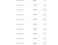
I also checked with my store that the value of capasitors that i can get there is capasitors 22,33,47 uf
Coils not lower than 100
Resistors not under 330
Some coils can be higher resistance with no problem. All that are in series with a resistor can. Some can be higher with some small changes. It is usually easier to find and less expensive to use higher resistance coils. Other times you can use iron cored inductors for lower resistance.
Which components look difficult to get?
Which components look difficult to get?
Some coils can be higher resistance with no problem. All that are in series with a resistor can. Some can be higher with some small changes. It is usually easier to find and less expensive to use higher resistance coils. Other times you can use iron cored inductors for lower resistance.
Which components look difficult to get?
The small resistor and the coil at the picture
And the capasitors 27,36uf
Attachments
18 and 27 are E12 values and 36 is 2x18. I'm surprised you can't find them (what can you get?). Why not change them to E6 in xsim and choose one.
Smaller resistor values can be made by putting multiples in parallel. You don't always need to start with 5W units or things would get unnecessarily large.
The RLC near the woofer could be replaced with a series inductor, making a third order filter instead. It will be OK but not quite as good. I was thinking you might wind your own, or unwind a bought inductor, or just be lucky enough to find one.
Non-polarised electrolytic capacitors are a good place to start when experimenting. People talk them down but most of the time they are fine.
18 and 27 are E12 values and 36 is 2x18. I'm surprised you can't find them (what can you get?). Why not change them to E6 in xsim and choose one.
Smaller resistor values can be made by putting multiples in parallel. You don't always need to start with 5W units or things would get unnecessarily large.
The RLC near the woofer could be replaced with a series inductor, making a third order filter instead. It will be OK but not quite as good. I was thinking you might wind your own, or unwind a bought inductor, or just be lucky enough to find one.
Non-polarised electrolytic capacitors are a good place to start when experimenting. People talk them down but most of the time they are fine.
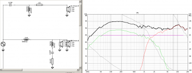
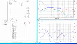
I am looking,but this is what i have found and testing it in xsim.
i tested too do series wired capasitors,but changed too be crazy🙂🙂
How do the impedance looks on your computer? the xo point and the graph doesnt look that bad?
Attachments
Last edited:
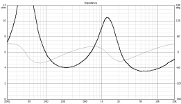
I tried retracing from Seas site. Also reducing sensitivity a little. This low impedance in the treble is the same as the original impedance.
I also noticed this coil.
I am doing right with my resistors?(100m was the minimum i can get) it look ok at the graph.
Attachments
Putting them in parallel is correct.
However, the 10m resistor is meant to be deleted. This is always true, as 10m is of no real effect. I just leave them there to save creating them again when I change my mind 😉
However, the 10m resistor is meant to be deleted. This is always true, as 10m is of no real effect. I just leave them there to save creating them again when I change my mind 😉
Putting them in parallel is correct.
However, the 10m resistor is meant to be deleted. This is always true, as 10m is of no real effect. I just leave them there to save creating them again when I change my mind 😉
Ahh okey,i will get you feedback after testing this setup,you have give alot of help! Thumbs up!
Thanxs.
- Status
- Not open for further replies.
- Home
- Design & Build
- Software Tools
- frd zma