I’ve spent a good bit of time searching through the threads for info on Frank’s 6SN7 preamp and regulated power supply – there’s a LOT out there to sort through. Apologies in advance if I’ve missed them, but I have a couple of issues/questions that I haven’t found an answer for:
First – the 5uF cap on the linestage output. What’s a good neutral cap that won’t break the bank? In the past, I have listened to Solens in the signal path, didn’t care for them. Maybe one of the Mundorf offerings? Which one? Skip the fancy parts and use a motor run oiler?
Second – on the regulated supply – how important are the two 150uF capacitors at the output? Can this capacitance be reduced (or eliminated) with a well filtered input B+, or does the ECL85 and/or 5651 introduce noise/ripple that requires filtering? I have junk box parts on hand for a nice dual mono CLCLC 350V supply for input to the ECL85, PSUD II sims <1mV ripple (finally found a home for those low current chokes). Yeah, regulation is probably overkill, but I haven’t ever built a regulated supply and it’s an inexpensive implementation, so why not? 😀
The bypass caps at the output of any regulator are to maintain the low output impedance at high frequency. Their quality is important; they need to be low ESR, ideally perhaps metallized polypropylene.
First – the 5uF cap on the linestage output. What’s a good neutral cap that won’t break the bank? In the past, I have listened to Solens in the signal path, didn’t care for them.
Have you tried bypassed Solens or other brand of metalized polypropylene part that's been bypassed? A Solen or GE metalized polypropylene 4.7 muF. part bypassed by a 0.47 muF. 716P series "Orange Drop" is pretty darned good. A refinement of the bypass idea is to use a 0.33 muF. PPFX Multi-Cap, instead of a 716P.
FWIW, the GE part # is 40L3471. Check with Madisound to see if they have any 40L3501s (5 muF.) left.
Thanks for the great responses - just what I needed. A couple of follow-ups:
OK, good to know. I need to read more, but building and measuring is half the learning process for me it seems. In the meantime, is there a formula or a "rule of thumb" on the amount of capacitance? I bought a couple of 100uF CSC motor run caps (metallized polypropylene in oil) at a surplus shop, would 100uF per supply be sufficient?
Maybe I have heard a bypassed metalized polypropylene, but didn't know it was bypassed because it didn't sound like a Solen. The 40L3471 appears to be available from some of the usual suspects, I'll give it a try with a 0.47uF bypass.
Hmmm, I have a couple of unused 0.47 RTX Multi-caps I bought for a project that changed; as long as I'm going overkill, why not?
The bypass caps at the output of any regulator are to maintain the low output impedance at high frequency. Their quality is important; they need to be low ESR, ideally perhaps metallized polypropylene.
OK, good to know. I need to read more, but building and measuring is half the learning process for me it seems. In the meantime, is there a formula or a "rule of thumb" on the amount of capacitance? I bought a couple of 100uF CSC motor run caps (metallized polypropylene in oil) at a surplus shop, would 100uF per supply be sufficient?
Have you tried bypassed Solens or other brand of metalized polypropylene part that's been bypassed? A Solen or GE metalized polypropylene 4.7 muF. part bypassed by a 0.47 muF. 716P series "Orange Drop" is pretty darned good. A refinement of the bypass idea is to use a 0.33 muF. PPFX Multi-Cap, instead of a 716P.
FWIW, the GE part # is 40L3471. Check with Madisound to see if they have any 40L3501s (5 muF.) left.
Maybe I have heard a bypassed metalized polypropylene, but didn't know it was bypassed because it didn't sound like a Solen. The 40L3471 appears to be available from some of the usual suspects, I'll give it a try with a 0.47uF bypass.
Hmmm, I have a couple of unused 0.47 RTX Multi-caps I bought for a project that changed; as long as I'm going overkill, why not?
You might have more luck with your questions if you post a link to the circuits. Not everyone has heard of 'Frank's 6SN7 pre".is there a formula or a "rule of thumb" on the amount of capacitance?
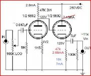
finally at a "real" computer; here are the schematics. I'm building the second, direct coupled version of the linestage
hope I have loaded these properly...


hope I have loaded these properly...
It's amplifying so you'll have to deal with the extra gain. Respect the max heater-cathode voltage (originally 90 volt for type 6j5).
Yes almost certainly. 2x150uF in the original circuit was real overkill.I bought a couple of 100uF CSC motor run caps (metallized polypropylene in oil) at a surplus shop, would 100uF per supply be sufficient?
It's amplifying so you'll have to deal with the extra gain. Respect the max heater-cathode voltage (originally 90 volt for type 6j5).
My amps are only two stage and really need an active pre, so that's good. I should be inside the heater/cathode rating for GTA/GTB tubes, but I do plan on lifting the heater voltage in case I use older types. I'm building it for 12v filaments - interesting tubes are a lot easier to find in 12v.
Yes almost certainly. 2x150uF in the original circuit was real overkill.
Great! Thank you!
I'm building it for 12v filaments - interesting tubes are a lot easier to find in 12v.
RES quotes $7 for 14N7s. The 14N7 is a "12" V. heater/Loctal based twin triode electrically equivalent to the 12SN7. 😉 Loctal tubes, regardless of branding, were made by Sylvania. Sylvania made 6SN7s get "drooled" over quite frequently.
I am currently running this preamp, sounds wonderful. I used a single 150uf cap per regulator, tried with two and found no difference in sound or measurements. YMMV.
RES quotes $7 for 14N7s. The 14N7 is a "12" V. heater/Loctal based twin triode electrically equivalent to the 12SN7. 😉 Loctal tubes, regardless of branding, were made by Sylvania. Sylvania made 6SN7s get "drooled" over quite frequently.
Shush! Don't let the secret out, prices will go up!
Actually, in my last two scratch builds I used 14N7's in phase splitter duty. Silly cheap for such a nice tube, and I had a few sockets in the junk box.
I am currently running this preamp, sounds wonderful. I used a single 150uf cap per regulator, tried with two and found no difference in sound or measurements. YMMV.
Thanks!
hi, is frank's preamp class a or push pull? would like to know shunt supply or series best for it.
It is single ended, what makes it sensitive to power supply imperfections and channel bleeding by default, to a certain degree. The input stage uses regenerative feedback so its operating point will be stable, compared to the bypassed cathode. The direct coupled version would be preferred both by purists and designers as the input stage gets less loaded. Its consequence will be reflected in diminished distortion and improved dynamic response. That might translate to an improved reproduction with the rest of your system, depending on one's taste. Measurement is not all in this situation.
In how far one type of regulator might be better than the other depends on the quality of the regulator itself, not on the topology. Measurements can be taken w.r.t. output impedance and phase/frequency dependency, above the first function as a ripple and noise eater. Series regulators demand more voltage than shunt regulators (which demand more current) what sometimes dictates the choice. Measurement is prevalent in this situation.
In how far one type of regulator might be better than the other depends on the quality of the regulator itself, not on the topology. Measurements can be taken w.r.t. output impedance and phase/frequency dependency, above the first function as a ripple and noise eater. Series regulators demand more voltage than shunt regulators (which demand more current) what sometimes dictates the choice. Measurement is prevalent in this situation.
Hi,
Very happy to hear you're pleased with the results but......
If you don't mind, let us put this design on it's historical context.
At the time of designing high quality, high value, film caps were rather unobtainable. 1990 or thereabouts.
Were I asked to redo this design now I would not go for a SN7 (whatever the variety) and I'd use some polyprops after the regulator iso of the elcos.
I'd still keep an elco after the reg to filter noise from the VR valve though sepated with a small series R.
And, they can be of far lower capacitance too with an advantage.
So why these caps? Well //ing them was one way to reduce their esr at HF (audio HF)
As said, if I had to do this again I'd probably go for a 6DJ8 (or similar gm/mu valve) as an SRPP DC coupled into a WCF using the same type of valve as a nice starting point.
The PSU can remain pretty much the same as demands are pretty low for such a simple design.
Using the SRPP stage gain would be very close to the SN7 stage but it would be potentially more detailed at the expense of added complexity.
As for the 5 microF output cap. Well, the value of this has been chosen so the stage would have extended bass response pretty much regardless of the amp it's driving.
If you know the input impedance of your amp, reduce or increase it's value as needed.
As for current regs as opposed to series regs, I'd dare anyone to use a shunt reg with this particular design and tell me it makes a world of difference.
IOW, to my mind I very much doubt it.
Using valved rectified (or hybrid) might possibly make an audible difference. I wouldn't bother with this design though. May use Schottkys to some benefit but again, the series reg will pretty much negate the effect as it cancels most RF nasties.
And isn't that what designing is about?
And yes, I should design a better 250VDC reg one day a la my 300VDC one too.....
Anyways, I hope this gives some more insight, 😉
I am currently running this preamp, sounds wonderful. I used a single 150uf cap per regulator, tried with two and found no difference in sound or measurements. YMMV.
Very happy to hear you're pleased with the results but......
If you don't mind, let us put this design on it's historical context.
At the time of designing high quality, high value, film caps were rather unobtainable. 1990 or thereabouts.
Were I asked to redo this design now I would not go for a SN7 (whatever the variety) and I'd use some polyprops after the regulator iso of the elcos.
I'd still keep an elco after the reg to filter noise from the VR valve though sepated with a small series R.
And, they can be of far lower capacitance too with an advantage.
So why these caps? Well //ing them was one way to reduce their esr at HF (audio HF)
As said, if I had to do this again I'd probably go for a 6DJ8 (or similar gm/mu valve) as an SRPP DC coupled into a WCF using the same type of valve as a nice starting point.
The PSU can remain pretty much the same as demands are pretty low for such a simple design.
Using the SRPP stage gain would be very close to the SN7 stage but it would be potentially more detailed at the expense of added complexity.
As for the 5 microF output cap. Well, the value of this has been chosen so the stage would have extended bass response pretty much regardless of the amp it's driving.
If you know the input impedance of your amp, reduce or increase it's value as needed.
As for current regs as opposed to series regs, I'd dare anyone to use a shunt reg with this particular design and tell me it makes a world of difference.
IOW, to my mind I very much doubt it.
Using valved rectified (or hybrid) might possibly make an audible difference. I wouldn't bother with this design though. May use Schottkys to some benefit but again, the series reg will pretty much negate the effect as it cancels most RF nasties.
And isn't that what designing is about?
And yes, I should design a better 250VDC reg one day a la my 300VDC one too.....
Anyways, I hope this gives some more insight, 😉
I can't quite understand about the schematic. If the circuit is like this the phase of the output signal will be ' a lot ' different from input. Won't it have an impact(may be a bad impact) to the amp?
I can't quite understand about the schematic. If the circuit is like this the phase of the output signal will be ' a lot ' different from input. Won't it have an impact(may be a bad impact) to the amp?
As long as both channels have the same phase shift it's ok.
But there is something wrong with the values in the schematic 😕
Mona
Attachments
Hi,
The current value stated beside the second section is wrong.
IIRC the B+ of the original design was much higher and the drawings haven't been corrected properly.
The circuit should still work fine. Just don't expect miracles from a CF using half a SN7.
Furthermore, the output cap doesn't need to be that big if you're driving a valve amp with say, 100K Zin and shortish interconnects.
Hope this helps, 😉
- Status
- Not open for further replies.
- Home
- Amplifiers
- Tubes / Valves
- Frank’s 6SN7 pre & regulated supply