The lady hasn't sung yet, so it ain't over. I just had to add a 3 pin connector, J5, for an off-board digitally controlled relay for Vds on/off switching. This is an optional safety feature in case Vgs is not present. There are readily available digital relays for Arduinos so it's an easy decision. Just a little extra programming.
Maybe, now the singing starts.
Maybe, now the singing starts.
Attachments
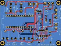
I received my PCBs from JLCPCB today. Well actually, they arrived in Canada over a week ago, but the package sat in customs for 4 or 5 days, and then with the long, holiday weekend, another delay. Needless to say, after receiving it, I was anxious to see if my $6 paid off or not.
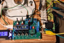
After a couple of hours cleaning up my work area, getting all the parts together, and finally soldering everything to the circuit board, I had just enough time before my afternoon nap to test it out. Luckily, everything worked. Well, I didn't test it with an external power supply; just used the internal USB 5V, but other than that, all the knobs and switches did what they were supposed to do.
So, I'm pretty happy. I'll do some more testing tomorrow. Now, it's either nap time or snack time. Soldering gives me an appetite.
Attachments


I tested the device with an external power supply yesterday and things worked as intended. It is time to release it into the wild.
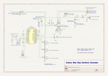
The schematic has been updated with part numbers for components which are dictated by their PCB footprint, electrical rating, or software/hardware compatibility.
I have uploaded the Gerber files for the circuit board as well as the Arduino program. Probably tomorrow, I will write something up explaining the program logic. This may be of interest to those who are not familiar with Arduino programming.
There is one feature that I have not yet fully implemented. That is the Arduino controlled relay for Vds. There is a terminal block on the PCB ready to accept a digital controlled relay, but I don't have one on hand so I have not programmed the software for it. I'll get one on my next parts order and finish the programming. The relay I have in mind is the DFRobot DFR0017 non-latching relay. Having a relay on the Vds circuit is not necessary, but it's nice to have the Vds switched off automatically if Vgs is not present, and this relay is very reasonably priced.
The operation of the device is fairly straight forward. A toggle switch selects the mode (Set/Run) while another sets positive or negative bias voltage. Three potentiometers are used to set the voltage lower limit, upper limit, and step size of the output waveform. A fourth pot varies the frequency of the waveform for phase synchronization with the Vds waveform.
There is one calibration procedure that needs to be performed before first use. The the software calculations require the voltage applied to the digital potentiometer. An Arduino analog input port is used to measure this, but since its maximum allowable voltage is 5V, the input to the port must be scaled so its magnitude does not exceed 5V. The external voltage input is limited to about 14V with the zener/LED/resistor circuit, so the POT5 voltage divider must be adjusted to divide the input voltage by 3 to keep it below the 5V limit. Once this calibration is done, the software computations with multiply the voltage at the Arduino input by 3 to obtain the true value
To calibrate POT5, use a jumper at connection block J4 to select the Arduino internal 5V supply as the bias voltage source. Apply power to the Arduino and with Switch SW2 in Set mode, adjust POT5 until the display screen shows the correct voltage. This should be approximately 5V; you can measure the voltage at J4 for a more precise value.
Populating the circuit board is fairly easy with the exception of the DS3502 digital pot IC. This is a tiny surface mounted 10 pin MSOP device. There are a few options to implement this. The simplest, although not necessarily the easiest, is to solder it directly to the PCB pads. The next less stressful method is to solder the SMD to a DIP breakout board and then solder that to the PCB. The last option is to purchase an Adafruit DS3502 breakout board and connect it to the DIP pads on the PCB with solid core wire. I have not made provisions for directly mounting it to the PCB, The Adafruit board is quite small so using wires to attach it to the PCB should not be an issue. Anyways, it fits the Frankentracer theme.
That's it for this post. More to come ...
Attachments
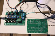
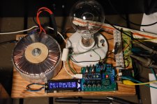
My Frankentracer is physically complete. I removed the original bias components and added the new Arduino bias circuitry to the Frankentracer board.
I received the DFRobot digitally controlled relay (DFR0017) and that has been incorporated into the Arduino system as well. The DFR0017 is a mechanical relay controlled by digital logic. It makes a audible "click" sound when it turns on or off and its status is also indicated by a red LED.
The relay is used to control the power to the drain of the device under test. The Arduino will disconnect power to the drain when the user is configuring the test during "Set" mode, if no bias voltage is detected at the input to the digital potentiometer, or if the Arduino loses power and is no longer outputting the bias waveform.
During my tests, I found this relay feature to be very useful. By toggling the mode switch from "Run" to "Set", Vds is disconnected before Vgs is turned off. I don't have to worry about pulling the plug or setting the Variac to zero. Handy when tracing multiple devices for matching.
The revised Arduino software to come.
Attachments
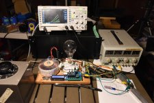
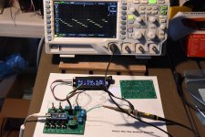
Yesterday and last night when I was testing the improved Frankentracer, I was not happy with the traces all appearing simultaneously on the oscilloscope. That is, they were not always all visible. I messed around with the triggering, sampling, and also frequency on the Arduino output, but I had to work hard to get a good picture.
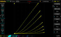
After a good night's sleep, I decided that the check I added to the code to turn off Vds if no bias voltage input is present was slowing things just enough to give me grief. So, this morning I found an AnalogReadFast() function library by Albert van Dalen which greatly improves on the performance of the Arduino analogRead() function. With the new function substituted in, I definitely noticed that it was easier to generate the family of curves on the oscilloscope screen. I can live with the result.
The Vds relay switch is really not necessary to the function of the Frankentracer, but I believe that it is a good thing to have.
Oscilloscope screen plot of my Russian test SIT curves and Arduino code are attached.
Attachments
- Home
- Amplifiers
- Pass Labs
- Frankentracer created