Scratching An Itch:
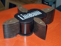
I’ve always liked the look of stacked plywood construction and always have wanted a pair for myself. However stacked ply often causes more headaches and concerns than it’s unique appearance justifies. Wesayso’s gorgeous line arrays suffered some delamination after hundreds of hours of sweat equity. Stacked ply can be fairly criticized for poor utilization of material, all those cut-out pieces may go to waste. Birch ply can be a bear to finish, sometimes taking stain very unevenly. All that said, I still wanted a pair.
A sale at the local hardwood outlet enabled me to pick up a couple of 4x8 sheets of birch ply fairly cheaply. Some RatShack - Lineaum tweeters were hanging around waiting to be utilized and there was a sale on at Solen for the SB acoustics SB13PFC25-08. What the hey; this’ll be fun and cheap.
Some years ago I had utilized the Optimus variant of the RadioShack / Linaeum tweeter with a couple of Vifa 5 inch mid woofers to build one of my ABS pipe transmission lines. These earlier speakers are bipolar at the mid woofers and dipoles on the tweeters. The result was very pleasing and I still have these in my downstairs system. More of the same would serve the purpose, quite a bit more.
I envisioned a stacked ply box with the tweeter on top, and a mid woofer on each of the four sides. the mid woofs being all in phase as an omni-pole.
I like ABS pipe so I’m going with an end terminated transmission line loading with four 4 inch ABS pipes exiting the bottom of the box. Initially I’m going to tune for 55 hz, some 10 hz above the published Fs of this driver. Utilizing pipe one can approach line tuning experimentally by adding or subtracting pipe. A quick consult with Martin King’s alignment tables gives a line length of 1.6 meters for an un-tapered line. Whoa, thats five feet of line repeated four times for each speaker. Hmmm…. Gonna need a lot of elbows. Another quick consult, this with Dave at Planet 10, warned me of interactions between the pipes terminating in a single plenum. So, okay, I’ll partition the plenum into four chambers one for each driver and it’s line.
The crossovers will be outboard to facilitate tweaks and rebuilds. Initial values will be cookbook solutions derived from published data and gleanings from web searches.
I realize that my design approach does not take advantage of the available art in modeling either the acoustic properties of the transmission line or the electrical properties of the crossover network. I am rather math challenged and a Mac guy to boot so I haven’t been able to run modeling software and would end up confused and depressed if I could. So what the hell I’ll just start whacking with a machete and clean up the mess afterwards.
Attachments


Whacking Wood
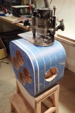
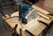
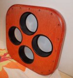
Needing to get enough squares of 18mm ply to get a stack 30cm high from the 4x8 sheets necessitated cutting the sheet into 3 strips of 6 squares 15.5 x 15.5 inches. Two squares would be laminated for a removable bottom and two squares laminated for the integral top. All squares were radiused at the corners by about 8cm.The remaining squares had their centers removed making a 33cm square hole. The box wall thicknesses were to be about 1.25 inches, this was reduced in finishing to a little over an inch. I built a little radius jig for my jigsaw to round the corners and a locating jig for my plunge saw to cut the holes.
The bottom piece was routed with four 5 inch holes to accept glued in ABS coupling fittings.
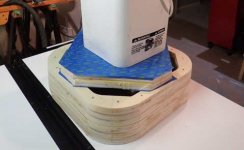
Mindful of the disappointment Wesayso suffered with his build I took a belt and suspenders approach to laminating the box. Building up from the laminated top piece I glued and screwed each layer. Every lamination was screwed to the one beneath it with twelve screws, I still worry that the internal laminations of the plywood will show cracks. After a day or two I had my box.
The bottom piece was screwed to the box for finish sanding.
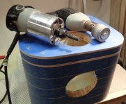
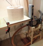
The vertical dimension of the box had been constrained by the working surface of my bench belt sander, about 12 inches. I was just able to sand the entire height of the box with one set-up. The belt sander did the fairing and rough finishing and final sanding was done with a palm sander.
Driver holes were routed in the four sides.
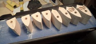
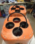
Next was probably the most difficult operation as the thick box walls needed to be relieved behind the driver openings. Since a bevel couldn’t be routed on the back of the baffle panel in the normal manner it had to be done from the front. The best solution was a rotary rasp in my router motor separated from it’s base, it could be hand held to make the 45deg bevel through the hole. Just don’t let Workmen’s Compensation see this rig, scary.
I now have a router table and I machined various radiuses on the edges.
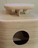
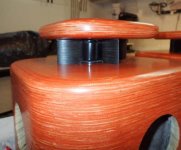
To mount the driver I chose to center it on the box top. A 10 in. x 10 in. x 1.5 in. top plate was conjured to cover the tweeter with its edges rounded with a parabolic round-over. As it could not be mounted directly on the lightly built tweeter I chose to through mount 4 .25 in. bolts through 4 stand-offs. I got a little tricky here and contoured the stand-offs with ogival profiles hoping for some phase-plug or wave-guide benefits. The “back” stand-off is wider than needed to conceal the tweeter wiring connections. Threaded inserts were applied in the box top to accept bolts through the top plate and stand-offs.
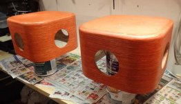
At this point I stained and finished the wooden parts.
After finishing I installed the interior baffles which will isolate each each driver in it’s own pre chamber. These were made from .25 in. birch ply and stiffened with hardwood battens. After fitting them inside the box they were simply welded in place with silicone seal; this turned out to be a very secure fastening.
Needing to get enough squares of 18mm ply to get a stack 30cm high from the 4x8 sheets necessitated cutting the sheet into 3 strips of 6 squares 15.5 x 15.5 inches. Two squares would be laminated for a removable bottom and two squares laminated for the integral top. All squares were radiused at the corners by about 8cm.The remaining squares had their centers removed making a 33cm square hole. The box wall thicknesses were to be about 1.25 inches, this was reduced in finishing to a little over an inch. I built a little radius jig for my jigsaw to round the corners and a locating jig for my plunge saw to cut the holes.
The bottom piece was routed with four 5 inch holes to accept glued in ABS coupling fittings.
Mindful of the disappointment Wesayso suffered with his build I took a belt and suspenders approach to laminating the box. Building up from the laminated top piece I glued and screwed each layer. Every lamination was screwed to the one beneath it with twelve screws, I still worry that the internal laminations of the plywood will show cracks. After a day or two I had my box.
The bottom piece was screwed to the box for finish sanding.
The vertical dimension of the box had been constrained by the working surface of my bench belt sander, about 12 inches. I was just able to sand the entire height of the box with one set-up. The belt sander did the fairing and rough finishing and final sanding was done with a palm sander.
Driver holes were routed in the four sides.
Next was probably the most difficult operation as the thick box walls needed to be relieved behind the driver openings. Since a bevel couldn’t be routed on the back of the baffle panel in the normal manner it had to be done from the front. The best solution was a rotary rasp in my router motor separated from it’s base, it could be hand held to make the 45deg bevel through the hole. Just don’t let Workmen’s Compensation see this rig, scary.
I now have a router table and I machined various radiuses on the edges.
To mount the driver I chose to center it on the box top. A 10 in. x 10 in. x 1.5 in. top plate was conjured to cover the tweeter with its edges rounded with a parabolic round-over. As it could not be mounted directly on the lightly built tweeter I chose to through mount 4 .25 in. bolts through 4 stand-offs. I got a little tricky here and contoured the stand-offs with ogival profiles hoping for some phase-plug or wave-guide benefits. The “back” stand-off is wider than needed to conceal the tweeter wiring connections. Threaded inserts were applied in the box top to accept bolts through the top plate and stand-offs.
At this point I stained and finished the wooden parts.
After finishing I installed the interior baffles which will isolate each each driver in it’s own pre chamber. These were made from .25 in. birch ply and stiffened with hardwood battens. After fitting them inside the box they were simply welded in place with silicone seal; this turned out to be a very secure fastening.
Attachments
-
 Finish.jpg33.8 KB · Views: 102
 -
 Prefinish.jpg31 KB · Views: 98
 -
 Standoffs.jpg29.2 KB · Views: 100
 -
 Mass destruction.jpg35.4 KB · Views: 118
 -
 Driver Holes.jpg33.3 KB · Views: 104
 -
 Belt Sand.jpg27.4 KB · Views: 106
 -
 Glue and Screw.jpg24.1 KB · Views: 251
 -
 saw jig.jpg34.9 KB · Views: 254
 -
 corner jig.jpg26.7 KB · Views: 254
Laying Pipe
Fabricating the ABS pipe transmission line bases is where my prior experience came in handy. I knew that the pipe would give me a solid structure to hold up the, now heavyish, boxes if it was made structurally stiff at the bottom level. I knew that I wanted to turn the pipe 180 deg. at the bottom so I glued two 90 deg. elbows to make a 180. I did this 8 times. I then glued and screwed the upper female sockets to a cruciform of stacked plywood which gave the same center to center pipe spacing as that on the bottom of the box.
At the bottom of the 180 deg. pipe elbows where the pipe was doubled at the glue joint I drilled holes and applied .25 in. thread inserts. I had previously made and finished a cruciform of 18mm ply to connect the four U bottoms. The cruciforms were given some leveling footers and bolted to the U bottoms with .25 in. bolts.
The result was a quite stiff base on which to build.
I cut some ABS connector pieces into single female sockets and glued these into the holes previously cut into the box bases. Using these sockets gives a durable and solid connection to the pipe as like all ABS sockets they have a specified taper.
All the rest is Lego-like assembly.
Attachments


Assembly Required
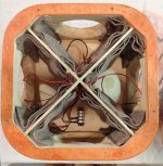
The boxes were lined on the insides with some layers of old wool blanket.
Interior wiring was put in place to wire the drivers; two series pairs in parallel. I used a skookum terminal block to connect the wiring in the “back” chamber. As the cross-overs are to live outboard I used a section of four conductor cable which is mounted to the box base and connected to the terminal block. Using the four conductor cable gives me the option of changing tweeter polarity without disturbing the speaker itself as it’s a bear to open up.
The tweeter was attached and connected to the box top and the top plate and stand-offs all bolted together.
Closed cell weatherstripping was applied to the box bottom piece to seal both the inside of the box from the outside and each chamber from the others. The box bottom was secured to the box with 20 2.5 in. screws, belt and suspenders.
Pipe was cut to length so that in combination with the pipe base and the speaker box the tweeters are located the standard 36 in. above floor level.
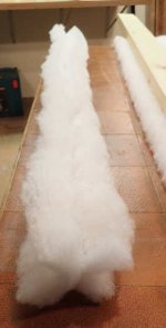
Polyester quilt batting was used to stuff the lines, it is lightly fused together and can be readily pulled through the pipe lines. Also it has a rather open weave and I estimated that in these narrow lines were not likely to render them aperiodic. I cut strips a little more than 4 in. wide and as the material is only 1 in. or so thick i stacked 2 pieces and ran a line of stales down the center of the strips to fix them together. I teased the 1.1 meter long strips into cruciforms and pulled them through the lines; a good secure fit.
Many dollars were spent buying elbows to curl the lines up and around the bases but we got er done.
The project was “erected” in the living room and after dropping the boxes on the assembled lines my two Frankenpuses were alive.
“Igor.. apply EL34 power”
“Yes Master”…….zzzt zzzt zzzzzttt
The boxes were lined on the insides with some layers of old wool blanket.
Interior wiring was put in place to wire the drivers; two series pairs in parallel. I used a skookum terminal block to connect the wiring in the “back” chamber. As the cross-overs are to live outboard I used a section of four conductor cable which is mounted to the box base and connected to the terminal block. Using the four conductor cable gives me the option of changing tweeter polarity without disturbing the speaker itself as it’s a bear to open up.
The tweeter was attached and connected to the box top and the top plate and stand-offs all bolted together.
Closed cell weatherstripping was applied to the box bottom piece to seal both the inside of the box from the outside and each chamber from the others. The box bottom was secured to the box with 20 2.5 in. screws, belt and suspenders.
Pipe was cut to length so that in combination with the pipe base and the speaker box the tweeters are located the standard 36 in. above floor level.
Polyester quilt batting was used to stuff the lines, it is lightly fused together and can be readily pulled through the pipe lines. Also it has a rather open weave and I estimated that in these narrow lines were not likely to render them aperiodic. I cut strips a little more than 4 in. wide and as the material is only 1 in. or so thick i stacked 2 pieces and ran a line of stales down the center of the strips to fix them together. I teased the 1.1 meter long strips into cruciforms and pulled them through the lines; a good secure fit.
Many dollars were spent buying elbows to curl the lines up and around the bases but we got er done.
The project was “erected” in the living room and after dropping the boxes on the assembled lines my two Frankenpuses were alive.
“Igor.. apply EL34 power”
“Yes Master”…….zzzt zzzt zzzzzttt
Attachments

Crossover Uncertainty
As I have stated earlier I am math challenged. I have no software for modeling other than the various java script web pages.
Web search gleanings on the Lineaum tweeter reveal little real data; my best information on it’s impedance comes from a sticker on the bottom which states 6 ohms.
The SB13PFC25-08 mid woofer is slightly better. Curt Campbell’s Uluwatu design uses this driver but he has incorporated baffle-step correction, a 7000hz notch and what appears to me as a 6 ohm series parallel system impedance which I am unable to reverse engineer for my 8 ohm system. Web musings indicate 2500hz at second order as a good crossover point for the SB13PFC25-08 with a possibility of using a third order to eliminate the 7000hz peak.
Start somewhere.
I will defy all proper advice, as seen in AllenB’s excellent tutorial, to account for woofer and tweeter impedance. I will improperly make a bunch of assumptions and enter… Crossover Hell.
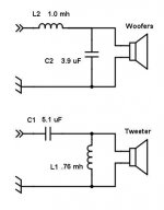
Assuming a woofer impedance of 8 ohms and assuming a tweeter impedance of 6 ohms and assuming I needn’t be bothered with baffle step considerations in an omnidirectional design I pack my assumptions off to the clever web page calculator at mh-audio.nl. After trying various combinations I settle on a second order L/R at 2500hz which gives values of 1.019 mH and 3.978 uF for the woofer and 5.303 uF and 0.764 mH for the tweeter.
I ordered the closest value parts and breadboarded them on plywood strips sized to fit in 4inch ABS pipe enclosures.
When the speakers were assembled and flashed up there was no magic smoke, imagine that. As to their suitability, more on that with the listening impressions and tweaks.
I am depending that the forum members will chime in on the crossovers to aid me in my shameful ignorance.
As I have stated earlier I am math challenged. I have no software for modeling other than the various java script web pages.
Web search gleanings on the Lineaum tweeter reveal little real data; my best information on it’s impedance comes from a sticker on the bottom which states 6 ohms.
The SB13PFC25-08 mid woofer is slightly better. Curt Campbell’s Uluwatu design uses this driver but he has incorporated baffle-step correction, a 7000hz notch and what appears to me as a 6 ohm series parallel system impedance which I am unable to reverse engineer for my 8 ohm system. Web musings indicate 2500hz at second order as a good crossover point for the SB13PFC25-08 with a possibility of using a third order to eliminate the 7000hz peak.
Start somewhere.
I will defy all proper advice, as seen in AllenB’s excellent tutorial, to account for woofer and tweeter impedance. I will improperly make a bunch of assumptions and enter… Crossover Hell.
Assuming a woofer impedance of 8 ohms and assuming a tweeter impedance of 6 ohms and assuming I needn’t be bothered with baffle step considerations in an omnidirectional design I pack my assumptions off to the clever web page calculator at mh-audio.nl. After trying various combinations I settle on a second order L/R at 2500hz which gives values of 1.019 mH and 3.978 uF for the woofer and 5.303 uF and 0.764 mH for the tweeter.
I ordered the closest value parts and breadboarded them on plywood strips sized to fit in 4inch ABS pipe enclosures.
When the speakers were assembled and flashed up there was no magic smoke, imagine that. As to their suitability, more on that with the listening impressions and tweaks.
I am depending that the forum members will chime in on the crossovers to aid me in my shameful ignorance.
Attachments
The Result
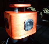
As you can see the Frankenpus looks…. impressive, weird, different… alive. I really like the look. They occupy quite a large footprint even though the lines are arranged to be as compact as possible. They are actually quite easy to move around with the footers offering pivots for the large speaker waddle maneuver. Dusting the black pipe will be a constant chore.
The sound…. impressive as well. Curt Campbell has said his Uluwatu design “likes to ROCK” mine do as well within reason.
I was floored by the bass response. At first go these five inch mid basses with their line ports contributing were off the hook. The bass response was deep and ample but flabby. I realized that my EL 34 tube amp was not controlling the bass adequately. As well the midrange and treble were submerged behind the midbass. The tweeter is apparently not as sensitive as is needed. the midrange had a bit of clang to it, my wool blanket treatment was not absorbing enough in-cabinet resonance.
First tweaks….
A pound of fiberfill stuffing was added into each box. This has killed the clang as well as helping out with the next tweak.
Two ohms of series resistance was added at the beginning of the woofer crossover. I think this paid huge dividends in both dropping the bass level to more closely match the tweeter and allowing the tube amp a more easily controlled load. There is much less flab at he bottom end. Now I’m thinking about room modes and their contribution to any lack of bass definition as I’ve had similar problems with my trusty old IMF TLS-80s.
I think my biggest problem now is that the tweeter can’t generate the sound pressure the four mid woofers are capable of. At high levels they can become a bit harsh. I also worry about longevity; these things were built a long time ago in a land far away.
In the meantime I find them enjoyable and look forward to getting them working their best.
Attachments


Last edited:
Bravo!! Great write up of your build. Best short story I've read in quite some time. Let your ears tell you if it's a success and it appears to be. Who needs those stinking calculators or programs to have a blast with this hobby anyhow. I admire your enthusiasm and craftsmanship. I will certainly follow this thread to see what other tweaks you may have up your sleeve.
Wes
Wes

Finish sanding
This was my favorite part of the build. With the edges all rounded over the sanding was surprisingly easy. There was no need to sand to perfection as I had intended a satin finish with a hint of end grain texture. It was a shame to put stain and finish on it, it felt so soft,warm and smooth.
This was my favorite part of the build. With the edges all rounded over the sanding was surprisingly easy. There was no need to sand to perfection as I had intended a satin finish with a hint of end grain texture. It was a shame to put stain and finish on it, it felt so soft,warm and smooth.
- Status
- Not open for further replies.
- Home
- Loudspeakers
- Multi-Way
- Frankenpus Build