Hi,
It's not clear to me what circuit you preferred, my buffered volume control or something else.
No need to move to the 1M attenuator, that's only critical if you use the phono stage ahead of it due to RIAA thingies...
No, not at all but if you want to push transparency one more notch use MKPs there, values can be way less like 200 to 100µF if you can find those in Brazil.
Cheers,😉
It was certainly worth the effort to build it. Now it´s time to build a nice wooden box and a 1M attenuator (today I used a 100k).
It's not clear to me what circuit you preferred, my buffered volume control or something else.
No need to move to the 1M attenuator, that's only critical if you use the phono stage ahead of it due to RIAA thingies...
Instead of using 330muF after the bridge and 2x 330muF after the regulation I am using 560muF (cap´s from a dismantled Audio Note amplifier) after the bridge and 2x 220muf (blue Philips) after the regulation. Will this cause problems?
No, not at all but if you want to push transparency one more notch use MKPs there, values can be way less like 200 to 100µF if you can find those in Brazil.
Cheers,😉
Hi Frank
I compared your buffered volume control with a simple 100k ladder attenuator.
Your buffered volume control made music sound much better.
Erik
I compared your buffered volume control with a simple 100k ladder attenuator.
Your buffered volume control made music sound much better.
Erik
Hi,
Thank you...
Next is that OTL amp, right?
Just kidding, Erik....😉
Your buffered volume control made music sound much better.
Thank you...
Next is that OTL amp, right?
Just kidding, Erik....😉
OTL
Your are right Frank. The next project is the 6AS7 OTL. Monoblocks with 8 output tubes/channel. No differential input stage, because I haven´t (yet) figured out how to implement it.
The actual building will start pretty soon, because: 1 - I have holidays; 2 - collected most of the components; 3 - drawn the layout for the PS (seems an industrial power factor correcting bank); 4 - built the chassis for one amplifier.
The actual amplifier chassis will be pretty neat, white and not to large.
The power supply chassis will be a great square wooden box. Just the EI trafo measures 18x14x18cm. Add the (some non-electrolytic) caps to this... I am thinking about putting the amplifier chassis on top of the power supply chassis, but not sure if this is good, because the trafo can´t lose it´s warmth this way. Probably will use the PS chassis as weight to firm the dipole speakers. 😀
Keep you updated...with questions.
Erik
Hi,
Not a bad idea, really...
Errrr. I mean to think about a two store design...
Nonetheless, I used a ten tubed design and that has it all on one chassis.
The genius who designed the xformer for that OTL gave me a xformer that would probably cost an an arm and a leg nowadays but, the xformer is darn cool, quiet as a mouse and can put out twice the current I need from the circuit...
Which is why it's so quiet in the first place,I reckon, and so cool runing too.
Best, 😉
I am thinking about putting the amplifier chassis on top of the power supply chassis, but not sure if this is good, because the trafo can´t lose it´s warmth this way. Probably will use the PS chassis as weight to firm the dipole speakers.
Not a bad idea, really...
Errrr. I mean to think about a two store design...
Nonetheless, I used a ten tubed design and that has it all on one chassis.
The genius who designed the xformer for that OTL gave me a xformer that would probably cost an an arm and a leg nowadays but, the xformer is darn cool, quiet as a mouse and can put out twice the current I need from the circuit...
Which is why it's so quiet in the first place,I reckon, and so cool runing too.
Best, 😉
Diff.input stage.
Hi
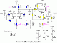
About the 6AS7 OTL . Frank, you talked about putting the ECC83 in a differential input stage, using both triodes. Looking at headwize today I found a headphone amplifier with an ECC83 in differential input stage. I attached the schematic.
Is this what you meant for the diff. input stage If yes...where should I connect the feedback?
Thanks
Erik
Hi
About the 6AS7 OTL . Frank, you talked about putting the ECC83 in a differential input stage, using both triodes. Looking at headwize today I found a headphone amplifier with an ECC83 in differential input stage. I attached the schematic.
Is this what you meant for the diff. input stage If yes...where should I connect the feedback?
Thanks
Erik
Attachments
Hi,
Actually, I think it was you who wanted it that way...Not me...
Look at the circuit of the ECC83 carefully and now look at the first stage of the Rozenblit amp using a 6SN7.
Hmmm, that's going to demand some polarity analysis...otherwise you may end up with positive feedback.
Any particular reason why you'd want it with a differential stage on the input?
Sure enough it's not going to give you a balanced input this way so I see little point in it.
Maybe someone else has a clearer view at 3.40 AM, I don't.
So, why not build it as is?
It's great sounding the way I suggested and gives you extra power to kick the woofers around.
Cheers,😉
Frank, you talked about putting the ECC83 in a differential input stage, using both triodes.
Actually, I think it was you who wanted it that way...Not me...
Look at the circuit of the ECC83 carefully and now look at the first stage of the Rozenblit amp using a 6SN7.
If yes...where should I connect the feedback?
Hmmm, that's going to demand some polarity analysis...otherwise you may end up with positive feedback.
Any particular reason why you'd want it with a differential stage on the input?
Sure enough it's not going to give you a balanced input this way so I see little point in it.
Maybe someone else has a clearer view at 3.40 AM, I don't.
So, why not build it as is?
It's great sounding the way I suggested and gives you extra power to kick the woofers around.
Cheers,😉
Just use the same specs for the xformer as per BR on a per channel basis, use the 12AX7A as a diff amp and put the 6SN7 in // to drive 8 tubes iso 4.
This is what you wrote in post 3 from this thread.
Hum...I've been a little hasty regarding the differential stage at the input.I had forgotten about the intermediate and driverstages.What you'd need is balun stage at the input using the 2 triodes of the 12AX7 and retain the gain of that stage....Than, there's the NFB loop to consider as well...
And this some further in the thread.
Best thing now is to stop thinking and asking (specially asking) and actually start building this thing.
Hi Erik,
True...When you read on from there you also read I had second thoughts about the idea and advised you against it.
That was the point I actually looked at the circuit and said to myself that there was no point in complicating it any further.
My mistake I suppose...
Ask all you like, I don't mind at all.
Cheers,😉
This is what you wrote in post 3 from this thread.
True...When you read on from there you also read I had second thoughts about the idea and advised you against it.
That was the point I actually looked at the circuit and said to myself that there was no point in complicating it any further.
My mistake I suppose...
Well, I will stop thinking and asking (specially asking) and actually start building this thing.
Ask all you like, I don't mind at all.
Cheers,😉
Hi Frank
I had the impression you discouraged me to built the diff. input stage because of my lack of knowledge about it.
Most of the times I feel silly asking basic questions at this forum. Reason 1: there are lots of sites (like tubecad) which tell me what I want to know. Reason 2: lots of experienced people at this forum may skip answering my questions, because I demonstrate lack of "basic" knowledge.
The solution: I ran out of money after buying componentes for your pre and Rozenblitz Power. The only thing I am able to do in the spare time of the next months is reading.
Have a nice week
Erik
Hi Erik,
Nah...I wouldn't do that.
The tube section of the forum is about the friendliest I know of, I don't visit all of the others but this is really a well behaved forum with great people.
Some may, a lot of people here will try to help you though, regardless.
Ouch....Yeah, quality doesn't come cheap...Just kidding....Brasil isn't particularly easy, I know.
Tubecad I hope...😀
And to you...Boa noit....(Good night)
Or something like that....Can't quite remember.
Cheers,😉
I had the impression you discouraged me to built the diff. input stage because of my lack of knowledge about it.
Nah...I wouldn't do that.
Most of the times I feel silly asking basic questions at this forum.
The tube section of the forum is about the friendliest I know of, I don't visit all of the others but this is really a well behaved forum with great people.
Reason 2: lots of experienced people at this forum may skip answering my questions, because I demonstrate lack of "basic" knowledge.
Some may, a lot of people here will try to help you though, regardless.
The solution: I ran out of money after buying componentes for your pre and Rozenblitz Power.
Ouch....Yeah, quality doesn't come cheap...Just kidding....Brasil isn't particularly easy, I know.
The only thing I am able to do in the spare time of the next months is reading.
Tubecad I hope...😀
Have a nice week
And to you...Boa noit....(Good night)
Or something like that....Can't quite remember.
Cheers,😉
Re: Diff.input stage.
Olá Erik-o -melhor!! 😉
The feedback, in the circuit you provide in post #26, must be connected to the point of interconnection of R5, R7 and R8.But it must be connected with a capacitor in series because there are DC voltage at this conecting point!
This circuit have not be designed with the aplication of global feedback in mind...but it can be done...😉
Um abraço para quem está no Verão...de alguem que está no Inverno!
ErikdeBest said:Hi
Is this what you meant for the diff. input stage If yes...where should I connect the feedback?
Thanks
Erik
Olá Erik-o -melhor!! 😉
The feedback, in the circuit you provide in post #26, must be connected to the point of interconnection of R5, R7 and R8.But it must be connected with a capacitor in series because there are DC voltage at this conecting point!
This circuit have not be designed with the aplication of global feedback in mind...but it can be done...😉
Um abraço para quem está no Verão...de alguem que está no Inverno!
Olá
Entre portugueses, brasileiros e pessoas que nos entendem...😀
Hi Frank.
I´ll read Tubecad and the likes. I want to reach the state where people just simulate amplifiers topologies (kidding). Well...at least it is cheaper.
e Jorge
Much thanks for your reply, but I won´t use it for the moment. I will stick to the design as published through Rozenblitz.... Well, not stick. 8 tubes per channel, parallel 6SN7, OB2 instead of zeners, bigger trafo, other kind of caps (more capacitance for 6AS7 PS and motor start caps for driver stage PS).
I haven´t seen much of a summer yet. We went to beach 26/12, returing 3/01/04, ie new year (reveillon) at the beach. It was raining, winding, and the smart people started at 1:20 in the morning with the fireworks. That time I was very comfortable, sitting inside the house and no chance to get out.
My name is actually Erik Jan de Best. No kidding about the "de best". Until now I suited me to get some free beers, won from people who didn´t believe I am a real "de best".
Hi,
What?... You guys thought you'd get away with it thinking no one would understand?
Think again...😉
Took me 2 years...I'm a trained and graduated philologist though, amongst other things...Solo mis pessoas...I bet that's Spantuguese...
Cheers,😉
What?... You guys thought you'd get away with it thinking no one would understand?
Think again...😉
I want to reach the state where people just simulate amplifiers topologies (kidding). Well...at least it is cheaper.
Took me 2 years...I'm a trained and graduated philologist though, amongst other things...Solo mis pessoas...I bet that's Spantuguese...
Cheers,😉
headwize headphone amp
The diff amp is used as a phase flipper with gain because you can't flip the phase at the headphone jack with a common ground. There is no feedback in this circuit, just gain and a ballsy cathode follower. I'll bet it sounds good.
MODS: Build a regulated (-) supply out of the filament supply, put a ccs diode in the diff amp tail to the (-) supply and GET RID of all the coupling caps except at the output. Let the CF float at the diff amp plate voltage, it's 30 volts away and regulate the b+ to the output tube.
Add NF at the r.h. triode grid will improve the bass, I'm sure. 10 db ought to do it (at the expense of gain).
- Status
- Not open for further replies.
- Home
- Amplifiers
- Tubes / Valves
- Frank´s pre and Rozenblitz power. Building them.