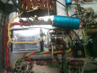
I have a FRANK pram 30 watts Ultra-linear Stereo tube amplifier, in which I am replacing the selenium full wave rectifier with a diode full wave rectifier, I am also replacing the selenium bias rectifier with a diode, as well as replacing the electrolytics.
The details of the amp are below.
I have a schematic, but it is missing some vital info. The selenium rectifier had a forward DC resistance of 295K and was pushing out 345V. As selenium rectifiers don't age well, I don't know if the 345V being output is too high or too low. As the forward resistance of the diode rectifier is much lower, the output is going to be much higher. What I am trying to find out is what the original design voltage should be. I'm not worried about the bias voltage as it's for the 4 x EL84 so should be about 11.5V I'm guessing.
Does anyone have any info on this amp?
Made in Belgium by the FRANK factory at the end of the 1950-early'60.
It uses an ULTRA LINEAR circuit, and the famous beige Philips-Mullard mustard capasitors.
Still complete factory original, all cap's and resistors are still original.
These FRANK amplifiers were all handmade.
This one was made March 1961.
2 x 15 Watt.
The tubes are : 4 x ECC 83 / 2 x ECC 82 / 4 x EL 84.
Works on 110 & 240 volts , speakers 8 - 16 Ohms


New diode rectifier.

The details of the amp are below.
I have a schematic, but it is missing some vital info. The selenium rectifier had a forward DC resistance of 295K and was pushing out 345V. As selenium rectifiers don't age well, I don't know if the 345V being output is too high or too low. As the forward resistance of the diode rectifier is much lower, the output is going to be much higher. What I am trying to find out is what the original design voltage should be. I'm not worried about the bias voltage as it's for the 4 x EL84 so should be about 11.5V I'm guessing.
Does anyone have any info on this amp?
Made in Belgium by the FRANK factory at the end of the 1950-early'60.
It uses an ULTRA LINEAR circuit, and the famous beige Philips-Mullard mustard capasitors.
Still complete factory original, all cap's and resistors are still original.
These FRANK amplifiers were all handmade.
This one was made March 1961.
2 x 15 Watt.
The tubes are : 4 x ECC 83 / 2 x ECC 82 / 4 x EL 84.
Works on 110 & 240 volts , speakers 8 - 16 Ohms
New diode rectifier.
Last edited:
Looks like a beaut!
If you can figure out how many "cells" were in the selenium rectifier, then you can figure out what the voltage drop should have been. Roughly 0.9 - 1v per "cell". If you want similar characteristics, you can add a 5W or 10W resistor in series with the diode to affect the same voltage drop and some amount of current limiting.
Better, if you can find out what the B+ "should" be, work to that. Since it's also likely that mains voltages have increased, you can factor that in at the same time.
All that said - if it's high by 5-10% - it is probably not going to cause a huge problem, provided you can set bias correctly.
I should add. 1v/cell is at low current. If the amp loads it quite a bit, you'll want to factor in the series resistance too, somewhere 100-200 ohms and as you surmise likely increases as the device ages. Should get you close to the mark if you can't find service data.
Did you use UF5408 for the replacement diodes? and what are the part numbers of the selenium stacks?
What a beauty!
345 VoltsDC is a very good choice of B+ for type EL84's. You're fortunate that the amp has a 240 VAC primary, pretty close to current line voltage in the UK, IIRC. In America, amps of this era were made for considerably lower line voltages than we see these days.
You doubtless already know how to deal with ancient power supply electrolytic caps and to check the coupling caps feeding the output valve grids, for current leakage.
Although I get a lot of push-back, I always recommend folks convert the ubiquitous common cathode resistors in the output stages to separate, individual resistors and bypass caps for each valve. Use a big cap, 470uF or 1000uF if it'll fit.
YOS,
Chris
I agree with the favorable assessment of the piece. 
15 WPC from PP EL84s, for 30 W. total, is very reasonable. OTOH, 30 WPC is utter nonsense. Rules and regulations regarding amplifier power claims were tightened up, after that beauty was built.
15 WPC from PP EL84s, for 30 W. total, is very reasonable. OTOH, 30 WPC is utter nonsense. Rules and regulations regarding amplifier power claims were tightened up, after that beauty was built.
This newer, 13W/channel model might be similar. I would add some rubber grommets in the chassis holes
that have wires going through them. Just cut the grommet so it can go around the wires and into the hole.
Frank Pram 40 Stereo Integrated Amplifier Manual | HiFi Engine
that have wires going through them. Just cut the grommet so it can go around the wires and into the hole.
Frank Pram 40 Stereo Integrated Amplifier Manual | HiFi Engine
Last edited:
Did you use UF5408 for the replacement diodes? and what are the part numbers of the selenium stacks?
The diodes used are 1N5408.

I tried looking the numbers up, but didn't get very far.
What a beauty!
345 VoltsDC is a very good choice of B+ for type EL84's. You're fortunate that the amp has a 240 VAC primary, pretty close to current line voltage in the UK, IIRC. In America, amps of this era were made for considerably lower line voltages than we see these days.
Chris
Strangely although the given voltages are 110/240 the voltage selector is marked at 110/130/145/220/245

Seems like the first number on the rectifier is the voltage rating and the second is the current in mA. But just writing that made me think of 'granny sucking eggs'.
Thats correct, but these things are all built the same so if you have a datasheet for a part with similar characteristics you can use that datasheet.
Seems like the first number on the rectifier is the voltage rating and the second is the current in mA. But just writing that made me think of 'granny sucking eggs'.
Last edited:
For anyone who speaks French or wants to spend the rest of the week on Google translate. 😀.
Here is a pdf of the pamphlet that comes with the amp', it includes a schematic.
https://cursorium.co.uk/images/Frank_Pram_30.pdf
Here is a pdf of the pamphlet that comes with the amp', it includes a schematic.
https://cursorium.co.uk/images/Frank_Pram_30.pdf
Update on the above:
I managed to OCR the pdf online, then put it through Google translate, then save it as a pdf.
It's not perfect, but at least it is in English........ Sort of 🙂
https://cursorium.co.uk/images/Frank_Pram_30-eng.pdf
I managed to OCR the pdf online, then put it through Google translate, then save it as a pdf.
It's not perfect, but at least it is in English........ Sort of 🙂
https://cursorium.co.uk/images/Frank_Pram_30-eng.pdf
Does anyone think that using Vishay UF5408 ultra fast soft recovery diodes instead of standard 1N5408 for the new power supply and bias rectifier will have any significant effect on lowering the power supply noise produced?
390V B+ - about 13% over the original.
Bias on the valves is 13.5V. So if I use a resistor to get me back to 345V the bias should go back to about 11.75V.
I have also changed the bias diode for the same type used in the rectifier.
Bias on the valves is 13.5V. So if I use a resistor to get me back to 345V the bias should go back to about 11.75V.
I have also changed the bias diode for the same type used in the rectifier.
Last edited:
That's a lot, didn't know selenium rectifiers were that inefficient. Did you also experiment with adding a series resistor for each diode? May be that will be more effective in smoothen the PS noise than a (larger) single resistor after the rectifier. Won't look original then 😉
What voltage do you measure at the EL84 anodes? They will have a short life at anything over 340 volts in fixed bias...
You could measure the total current draw if you measure the voltage drop across the 50Ω
resistor from the rectifier (eg by Ohms law, 8 volts would equate to 160mA and so on.)
From that you can guestimate the dissipation of each EL84 and try and keep it below 14 Watts each... some EL84s are not as good as others.
- Home
- Amplifiers
- Tubes / Valves
- FRANK pram 30 watts Ultra-linear Stereo tube amplifier.