
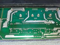
Board is short of driver transistors, but might be usable as is as an output transistor board. Trace out where the base lines go. If to those standard looking connectors, you're in. If those grey blocks are sub 1 ohm resistors from emitters to parallel outputs, also good.
All those little resistors are weird , though.
Datasheets will be on datasheetcatalog.com. Use 1/3 the Vceo value as maximum rail voltage.
This leaves you with a monaural amp, though. To get stereo you would have to separate the transistors into two pairs on different boards.
Output transistors go as low as E1 this week, so don't get too excited over your find.
Driver boards could be LME49811 based like Mircea's work with layout , www.neutrine-system.com. At the time he posted he would sell boards to europe, but not elsewhere. Or drivers from Peavey PV500,PV1500, PV4, or PV8. The latter you would have to lay out your own boards, only the schematic is available on line . Long parallel runs of the base drive and the feed back line are not recommended due to possible oscillation. Keep the base drive separate from the collector feed lines, too. Flying wires were the standard in the separate driver board-output transistor days.
The lack of fins on the heatsink indicates the vendors were using the case as aheatsink. This allowed companies to sell amps with an impressive rating when the advertised rating was a one hour rating, but if you intend to use the amp longer than that, you need a heatsink with fins and/or a fan.
Last edited:
Give that thing a good scrubbing in the shower before you do anything with it. Use soap too. Let dry outside for a couple hours. I always do this with dirty old amps. Gets real nice to work with.
Obviously, you can build your own driver or use the still available LM4702 -- TI still has the application note on using this driver chip with MOSFETs. http://www.ti.com/lit/an/snaa045a/snaa045a.pdf
The author's name has been removed from the Ap Note, he used to be on DIYAUDIO from time to time.
The author's name has been removed from the Ap Note, he used to be on DIYAUDIO from time to time.
- Status
- Not open for further replies.