Hi, lazzer408
200K+200K+200K ?
how do they do balanced output from this phase invertor?
220k+220k+220k ?? Beats me. I'm just copying what I can from their p2p wiring. Maybe it was "good enough" for a mass produced budget console?
I also read 355v on the anode. The common cathode bias uses an 82ohm 10w resistor. I haven't measured the voltage across the 82ohm but I'm about to. I have one odd-ball tube red plating. All caps were replaced. The tube that's red plating is a 6BQ5 from the Magnavox amp. The rest are Motorola EL84.
I added a 33ohm with the 82ohm for 115ohm total. It has 12.8v across it. 110ma? /4 is 27.75ma per tube. It seems the right channel is red plating but the left is ok. As I mentioned the caps have been replaced. I'll check the grid resistors.
Last edited:
mmm, the difference isn't so big, maybe they just don't care about a little imbalace, and/or in the real life circuit , for some reason, it do not harm
Looks like all the resistors check out ok. With my hand I can feel more heat being radiated by the right channel then the left. It may be that the original Motorola tubes are weak causing more current to be forced through the Magnavox tube. I can swap the tubes left for right and the problem follows. Time for tubes.
I need someone to chime in on these paraphase splitters. The schematic in post #36 shows the phase invertor using negative feedback to adjust it's gain (I assume). What are the pros and cons to this method vs. a simple resistor divider on the PI's input?
Here's that schematic again.

Here's that schematic again.
Attachments
I need someone to chime in on these paraphase splitters. The schematic in post #36 shows the phase invertor using negative feedback to adjust it's gain (I assume). What are the pros and cons to this method vs. a simple resistor divider on the PI's input?
The paraphase splitter was popular in these console amps of this era, they sound quite nice IMO and it may be due to the fact that they are NOT perfectly balanced and impart a bit of second harmonic to the signal giving a more "single-ended euphonic" sound to the amp.
They were a low parts count cheap solution that was the name of the game in the competitive console market. If you dont already have it I suggest you pick up a copy of good 'ol Morgan Jones ED.3 and give it a good read. The various types of phase splitters are covered in good detail.
It's the way they control the gain of the invertor that I haven't seen before. I've seen paraphase used in many amplifiers but those amps divide down the output of the first triode to feed the PI.
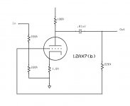
The Magnavox uses a common resistor divider with 470k and 39k to drive the PI grid. The Motorola uses a 220k and 220k divider -and- another 220k off the PI triode for negative feedback.
What are the pros and cons to each method?
Hi, to fine tune the invertor , just trim the lower tube 220K resistor (not the one that goes to ground) from the original value to some higher figure. Spice shows perfect balance with 255K, in the real circuit you need to try and measure. That's how you can control it. Variyng the amount of feedback. It looks more elegant than the Magnavox used method, but, You say you found it actually sound worse?
Last edited:
Out of the three resistors... There's one off the first triodes anode, another off the second triode's anode, and the third is from the second triode's grid to ground. Which of the three do you suggest changing? I'd suggest changing the resistor from the second triode's anode to it's grid. That one should be the negative feedback and control the overall gain of that triode.
I think this Motorola sounds better then the Magnavox actually. I'm only doing an ear comparison though. I haven't had the time to inject waveforms and see which is more "electrically correct". Musically, the Motorola has a warmer tone but treble is just as clear as the Magnavox. The Motorola's stage is also better, if I'm using that term right. The music seems to surround me more rather then come from the speakers themselves. When I separated the Magnavox's output tube common-cathodes, and used two resistors instead, I think it lost some of it's stage. The Motorola uses common cathode output tubes like the Magnavox used to and it isn't modified.
I'm now tempted to install a switch to toggle between the common cathode bias and separated bias. A DPDT should do the trick.
Would you have time to do another emulation if I provided the Motorola version of phase inverter?
Last edited:

Hi, I mean this one:
What do You need to check on Spice?
Yes that's the one that made sense to me.
Here's the Magnavox PI. I'm curious how symmetrical it is.
Attachments
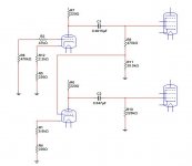
what's B+ on top of R6/R7? (ie after the supply decoupling resistor)
~295v

Thank you.
Interesting. It's not symmetrical either. Looks like almost 1v more negative swing on the orange waveform. Any idea what's causing it?
I like the Motorola PI better.
Interesting. It's not symmetrical either. Looks like almost 1v more negative swing on the orange waveform. Any idea what's causing it?
I like the Motorola PI better.
Magnavox Paraphase PI
Gabe provides a good explanation of the PI circuit and feedback network. As well as mods he made to the amp.
Magnavox Paraphase 15 wpc P-P Amplifier
Push Pull Tube Amplifier
Steve
Gabe provides a good explanation of the PI circuit and feedback network. As well as mods he made to the amp.
Magnavox Paraphase 15 wpc P-P Amplifier
Push Pull Tube Amplifier
Steve
Gabe provides a good explanation of the PI circuit and feedback network. As well as mods he made to the amp.
Magnavox Paraphase 15 wpc P-P Amplifier
Push Pull Tube Amplifier
Steve
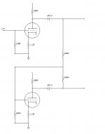
I've read that. I'm not talking about the Magnavox amplifier's GLOBAL negative feedback. I'm interested in the way the Motorola's PI used feedback from the PI's anode back to it's grid to adjust the gain of that triode.
This is the second triode in a paraphase inverter. The first being the triode getting the audio signal. The output from the first triode is fed into the second triode to be inverted. The gain of the second triode is adjusted via. negative feedback via. 220k resistor back to the grid. I typically see paraphase invertors use a simple resistor divider on the second triode's grid.
Which method is better?
Attachments
Well, in the Magnavox circuit there is a different bias for the second triode , there are different coupling caps, and different grid leak figures, I'm not an expert, but I was told in this forum, a while ago, that probably it was a cheap way to avoid oscilations and motorboating, annoyances much worse than some little imbalance.
I like best the Motorola inverter, never seen before one alike, thanks for posting
And for the common outputs cathode resistors, they said it probably creates a (light) "wide stereo" sort of effect, probably that's why it's graceful to the ear...
I like best the Motorola inverter, never seen before one alike, thanks for posting
And for the common outputs cathode resistors, they said it probably creates a (light) "wide stereo" sort of effect, probably that's why it's graceful to the ear...
Last edited:
Let's look at this from a solid state point of view using an op-amp. If you want an overall gain of 10, would you set the op-amp's feedback for a gain of 100, then reduce the input (via resistor divider) to 1/10? Or would you set the op-amp's gain to 10 so the full signal can be applied to the input? From a noise point of view, I would think reducing the gain of the op-amp and applying more signal would reduce noise.
I wish I had a good emulator or test bench to compare the two.
I have 2 tube amps on my project list. One uses a pair of Magnavox bi-amp mono blocks and for the most part will be unmodified. The other is a stereo 6L6 PP 50w/ch. Both will use a single chassis. The 6L6 amp I'll build from scratch using some parts from an old National amplifier. I haven't decided what type of PI to use for that build though. A paraphase should have enough gain to drive the 6L6s which is why I'm interested in finding out more about them. My other option might be a cathodyne PI in front of some driver tubes. I don't think a cathodyne PI can drive 6L6s by itself.
I read somewhere in the forum that Tubelab got working an universal driver module that can drive anything... For a 50W job maybe a search in this direction can be justified.a stereo 6L6 PP 50w/ch. Both will use a single chassis. The 6L6 amp I'll build from scratch using some parts from an old National amplifier. I haven't decided what type of PI to use for that build though. A paraphase should have enough gain to drive the 6L6s which is why I'm interested in finding out more about them. My other option might be a cathodyne PI in front of some driver tubes. I don't think a cathodyne PI can drive 6L6s by itself.
Apparently a driver stage following a cathodyne PI is a "Williamson amplifier". I read about it a million times but didn't realize what I was looking at. I think that's the design I'll go with and make it on a PCB just in case I want to transplant it. This would be sort of a universal driver board. The values could be changed to suit a wide range of requirements.
The next step would be choosing the tubes. The stages would be as follows.
1. Preamplifier stage (1/2 dual triode)
2. Cathodyne phase invertor (1/2 dual triode)
3. Drivers (1 dual triode)
The entire stereo amplifier would then consist of 8 tubes (excluding any rectifier tubes). That would make for a nice symmetrical layout with 4 6L6s each having a little buddy in front of it, unless they're all on a small PCB. My concern is any crosstalk from the PI into the preamp (since their both in the same bottle) and also crosstalk between the two drivers for the same reason.
Any suggestions as to what tubes to use? Could 4 12AU7s provide enough overall gain? Maybe some the gain done in the preamp stage and the rest via. the driver stage?
- Status
- Not open for further replies.
- Home
- Amplifiers
- Tubes / Valves
- Found myself a Magnavox 9302-00