you say your using batteries? i was gonna say try a different wall socket then the one the speakers are plugged to.
you may be getting feedback from the speaker and the mic. if the mic is not facing the speakers does this sound go away?
you may be getting feedback from the speaker and the mic. if the mic is not facing the speakers does this sound go away?
Heavy filtered signal... problem solved..
Hi impsick thanks for your reply, I dont know what was inducing those strange noises... I just added a RF filter to the input of the in-amp and voila! Hum and buzz are gone! Only white noise is barely heard in the background at high volume levels (probably due to the cheap mic Im using for test purposes or opamp noise maybe?).
I dont know if this is the best solution but I think that signal quality wasnt affected.
Attachments
To all people they try construct the preamplifier that I proposed. What I have to point out is that; the construction of an electronic circuit it requires from equal theoretical and practical knowledge. It is impossible you achieve what you have theoretically calculated in a practical circuit if you do not know certain basic things. For example, i prefer always the gnd of signal it is independent from electric gnd. Many times the ready cables of microphones that are sold in the market they have linked the signal gnd with the metal jacket of XLR plug. This is unacceptable. For this it should not us touches the panic and we begin the questions before we examine with each attention - alone us – everything that passes from our hand. Also all the microphone inputs are very sensitive as they have very large gain. It is mandatory a careful shielding. Summarising, i use this preamplifier for electro acoustic measurements with the application “Speaker Workshop” and be very reliable in measurements with Behringer ECM8000. I quote below two measurements of the mic. preamplifier - by alone - to prove its reliability. And the measurements have been taken by the oscilloscope and not by sound card based software.
Output noise with input open & powered with 18Vdc, and with input gain & level controlls at full. The noise it is only 5,6mVrms
Transient response under a sqare wave of 10KHz. The bounces are very little and well dumped for a so difficult signal managed by the old NE5532. And the rise time it is very succesfull at 3,1ìsec.
Output noise with input open & powered with 18Vdc, and with input gain & level controlls at full. The noise it is only 5,6mVrms
An externally hosted image should be here but it was not working when we last tested it.
Transient response under a sqare wave of 10KHz. The bounces are very little and well dumped for a so difficult signal managed by the old NE5532. And the rise time it is very succesfull at 3,1ìsec.
An externally hosted image should be here but it was not working when we last tested it.
Evaluation of performance in the practice 1
Let’s to see now in practice the performance of mic. Behringer ECM 8000 and the mic. preamplifier. In the 3 photos below appears one typical measurement setup of a Mission 780 driven by a cheap Rotel 2 X 50Wrms amplifier. The cross over frequency of Mission 780 it is 2,5KHz. The amplifier is supplied with signal from a function generator and the curves have been taking from an analog/digital oscilloscope Hameg HM 507. The cost of each item is: 1)Behringer ECM8000 = 60€ 2)Mic. Preamplifier = 60€
Let’s to see now in practice the performance of mic. Behringer ECM 8000 and the mic. preamplifier. In the 3 photos below appears one typical measurement setup of a Mission 780 driven by a cheap Rotel 2 X 50Wrms amplifier. The cross over frequency of Mission 780 it is 2,5KHz. The amplifier is supplied with signal from a function generator and the curves have been taking from an analog/digital oscilloscope Hameg HM 507. The cost of each item is: 1)Behringer ECM8000 = 60€ 2)Mic. Preamplifier = 60€
An externally hosted image should be here but it was not working when we last tested it.
An externally hosted image should be here but it was not working when we last tested it.
An externally hosted image should be here but it was not working when we last tested it.
Evaluation of performance in the practice 2
Below are the curves. The top red curve is the output of function generator and the blue bottom curve is the output of mic. preamplifier.
1) Input signal sinus 1 KHz. Here we see the reproduction reliability and that the phase shift is almost 0 degrees between input and output.
2) Input signal sinus 10KHz. Here we see that exists a phase shift however the signal has the same shape between input and output.
3) Input signal sinus 20KHz. And here we see a phase shift and uniformity of signal between input and output.
4) Input signal sinus 100Hz. We see the same things as in the previous curves.
5) Input signal triangle 1KHz. Here we see the distorted output signal - caused from ECM8000 mic. - optically and not in percentage.
Below are the curves. The top red curve is the output of function generator and the blue bottom curve is the output of mic. preamplifier.
1) Input signal sinus 1 KHz. Here we see the reproduction reliability and that the phase shift is almost 0 degrees between input and output.
An externally hosted image should be here but it was not working when we last tested it.
2) Input signal sinus 10KHz. Here we see that exists a phase shift however the signal has the same shape between input and output.
An externally hosted image should be here but it was not working when we last tested it.
3) Input signal sinus 20KHz. And here we see a phase shift and uniformity of signal between input and output.
An externally hosted image should be here but it was not working when we last tested it.
4) Input signal sinus 100Hz. We see the same things as in the previous curves.
An externally hosted image should be here but it was not working when we last tested it.
5) Input signal triangle 1KHz. Here we see the distorted output signal - caused from ECM8000 mic. - optically and not in percentage.
An externally hosted image should be here but it was not working when we last tested it.
Re: Nice chassis
Hi frickecello
How are you? I am fine for the present, i hope the same and you. Yes indeed the chassis is sprayed with satin (semmi gloss) black enamel paint. I thing you can find easy a ready 1U chassis in the market with low cost. Tomorrow i will post 2 or 3 photos of the component and a tip of how to make your own silkscreen for the front panel.
Good night
Fotios
frickecello said:Hey Fotios you've got a really nice chassis, is it spray painted?
Hi frickecello
How are you? I am fine for the present, i hope the same and you. Yes indeed the chassis is sprayed with satin (semmi gloss) black enamel paint. I thing you can find easy a ready 1U chassis in the market with low cost. Tomorrow i will post 2 or 3 photos of the component and a tip of how to make your own silkscreen for the front panel.
Good night
Fotios
Interesting...
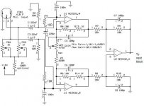
Sounds good Fotios, Im working on my own version I'm building an 8 channel mic preamp based on the classic in-amp topology, but with an aditional op-amp for linear gain control, some channels work great and some are noisy so I will need to do some troubleshooting, also I need an ultra quiet power supply... (any help will be appreciated) now Im working with an expensive precision lab power supply that is great for audio but is bulky and heavy.
I also added clipping led indicators using those nasty TL072 as comparators (the way they should be used, not for audio!)
Im using the good old NE5532, and lower value resistors to minimize noise, I will post an schematic soon to see what you guys think, what do you think about using the mitical 4558 for some channels?
Regards.
Marcello Fricke
Problem found?
I read and studied a lot about BJT input op-amps and found something interesting, the NE5532 has a BJT input stage whose input devices are NPN, so the bias currents flow into the chip! this means that if you tie a resistor from its input to ground you will have a negative bias voltage!
In the case of the LM833 whose BJT's inputs are PNP, currents flow out the chip, this means that if you tie the same resistor from its input to ground you will have a positive bias voltage..
This may sound obvious but then I thought about the excessive power dissipation problems that I have with my in-amp and the power supply instability.
I will change the NE5532's for LM833's, it seems logical that this may solve the problems that I currently have.
- Status
- Not open for further replies.
- Home
- Amplifiers
- Solid State
- Fotios's microphone amplifier