Hello !
Since I had exams I didn't have time to spend on DIY audio these days.
Now I'm on holiday and after having finished my Home theater system (I'm writing a part on it for my website) which works great, I thought I'd replace, as I foresaw it, my TQWT's for a better enclosure.
Well, I ran some simulations once more with MJK's outstanding MathCad sheets, and drew another TQWT design (I found it to model better than TL's or straight lines).
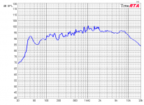
I built the prototype with a friend, sealed it perfectly and tested it.
Though 40Hz passes perfectly well, there is a lack between 100Hz and 50Hz that wasn't that deep in the simulation. Bass was rich and complex, but had no authority, consequence of the small size of the unit. Moreover, BSD decreases the bass output.
I then remembered something : Fostex didn't give the BL factor in its datasheet, and I estimated it to be 4.3 according to the efficiency of the driver. And then, I used CAAD4.1 to model a bass reflex enclosure, entered the driver parameters and was surprised to see that the BL calculated by the software from Fostex's params was not 4.3 but 5.16 !
Here was the key of the problem, and when I ran the simulation again, it became much more accurate, thanks to Martin's great work.
Well, though this enclosure is definetely better than the first one, I cannot accept such a frequency response !
I played arround with different enclosures types, but none of them can bring my FX120s down to 40-45Hz without linearity issues. Even at 50Hz, linearity is correct but not perfect
Double bass reflex looked really promising but a dip arround 100Hz makes it unusable. Does anyone has some tools to simulate a double chamber reflex, with 2 ports on the outside instead of one in MJK's sheet ?
Back loaded horns simulated using MJK's sheet gave me excellent results (peak impulse response, 30Hz...) but after 200Hz, the response presents some +10/-6dB spikes that are unacceptable. Judicious damping may correct the problem ?
Well, after all that, I decided to use the TL sections sheet, and filling it was really long. I thought increasing the surface of some sections of the TQWT judiciously and reducing some others to fill the lacks and damp the peaks could do the trick but right now I didn't obtain anything better.
The last idea I wish to explore would be a double TQWT/BR enclosure : a well tuned TQWT followed by a BR resonator or a TQWT including a resonator could maybe be able to bring the response down to 40Hz, but I doubt anyone has ever tried it. I suppose the DBR sheet isn't accurate enough to make the difference but maybe I'm wrong ! 😕
And then my philosophical point of view : MLTQWT's are in fact only BR which have judiciously used standing waves issues 🙄
Any comments welcome !
Since I had exams I didn't have time to spend on DIY audio these days.
Now I'm on holiday and after having finished my Home theater system (I'm writing a part on it for my website) which works great, I thought I'd replace, as I foresaw it, my TQWT's for a better enclosure.
Well, I ran some simulations once more with MJK's outstanding MathCad sheets, and drew another TQWT design (I found it to model better than TL's or straight lines).
I built the prototype with a friend, sealed it perfectly and tested it.
Though 40Hz passes perfectly well, there is a lack between 100Hz and 50Hz that wasn't that deep in the simulation. Bass was rich and complex, but had no authority, consequence of the small size of the unit. Moreover, BSD decreases the bass output.
I then remembered something : Fostex didn't give the BL factor in its datasheet, and I estimated it to be 4.3 according to the efficiency of the driver. And then, I used CAAD4.1 to model a bass reflex enclosure, entered the driver parameters and was surprised to see that the BL calculated by the software from Fostex's params was not 4.3 but 5.16 !
Here was the key of the problem, and when I ran the simulation again, it became much more accurate, thanks to Martin's great work.
Well, though this enclosure is definetely better than the first one, I cannot accept such a frequency response !
I played arround with different enclosures types, but none of them can bring my FX120s down to 40-45Hz without linearity issues. Even at 50Hz, linearity is correct but not perfect
Double bass reflex looked really promising but a dip arround 100Hz makes it unusable. Does anyone has some tools to simulate a double chamber reflex, with 2 ports on the outside instead of one in MJK's sheet ?
Back loaded horns simulated using MJK's sheet gave me excellent results (peak impulse response, 30Hz...) but after 200Hz, the response presents some +10/-6dB spikes that are unacceptable. Judicious damping may correct the problem ?
Well, after all that, I decided to use the TL sections sheet, and filling it was really long. I thought increasing the surface of some sections of the TQWT judiciously and reducing some others to fill the lacks and damp the peaks could do the trick but right now I didn't obtain anything better.
The last idea I wish to explore would be a double TQWT/BR enclosure : a well tuned TQWT followed by a BR resonator or a TQWT including a resonator could maybe be able to bring the response down to 40Hz, but I doubt anyone has ever tried it. I suppose the DBR sheet isn't accurate enough to make the difference but maybe I'm wrong ! 😕
And then my philosophical point of view : MLTQWT's are in fact only BR which have judiciously used standing waves issues 🙄
Any comments welcome !
Attachments
youyoung21147 said:Though 40Hz passes perfectly well, there is a lack between 100Hz and 50Hz that wasn't that deep in the simulation. Bass was rich and complex, but had no authority, consequence of the small size of the unit. Moreover, BSD decreases the bass output.
Why are you obcessed with 40Hz?
I doubt that this small driver can ever be linear down to 40Hz.
You should concentrate on the 50 to 60Hz region, that's where you should tune the BR.
Greets!
You do not mention what 'Sd' you used or whether you used published or measured specs, so WRT the 'BL' value, when I use published specs and a reasonable assumption for 'Sd', I arrived at 83.48 cm^2, 6.5133 N/A.
Pushing a driver this far below Fs requires lots of Vb and do not recall trying to get this far below without a huge horn, but now that we have MJK's WS, I plugged some Voigt style pipe numbers in and came up with a much better sim than I thought I would, though whether or not it will perform 'close enough' to prediction remains to be seen.
L = 114.7"
So = 1.567"^2 (pipe physically comes to a point)
SL = 157.08"^2
rp = 3"
lp = 2.28"
density = ~1 lb/ft^3 at pointed end only, with only some felt on one of the parallel side walls to damp any standing waves, so all damping experimentation should in theory only be done in the first ~23" of the pipe, though if you want to roll off the bottom more to improve transient response or better blend to the room, then add some on the 'floor' of the pipe.
Xo/zdriver = 0.682/~78.2" - IOW driver is up from the bottom ~36.5".
Obviously, due to its length it will need to be folded, so something like Bob Brines' Weems pipe variant, except with just a divider terminating at the bottom with no gap (to create a 'point') and the driver is so far down the pipe that it will be on the same face as the vent, which needs to be right at the bottom for lowest Fp: http://www.geocities.com/rbrines1/images/Weems_Pipe/Folded_Pipe.gif
FWIW, adding 4 ohms series resistance (Re = 11.3, Qes = 0.728) flattened it out and damped the slight peaking at Fp.
Anyway, if you build it, please let us know what tweaking you did and how well it worked, or not. For sure it will not play very loud, but in a small room may be adequate.
GM
I tend to agree with carlosfm, you can only push a 4.5" driver so far. The fx120 doesn't have a very large x-max either. Maybe you can push it so it will play 40Hz, but at the expense of power handling, and dynamics. Everything is a compromise.
Joe
Joe
Thanks for all these suggestions ! 😎
I'm not obcessed by 40Hz, but I noticed that almost every music I listen to goes down to 40Hz, and some even go down to 30Hz.
If I want to bring this speaker down to 40hz, it is because I cannot have a subwoofer (too expensive, and I don't have a good place for it anyway).
Dynamics are not really important because I never bring my speaker to its +-2 mm Xmax, except when I wanna listen to music out of my bedroom 😀. Anyway, the woofer displacement cannot be worse than on an open baffle.
I'm almost sure now that BR and DBR cannot bring this speaker down to 40Hz without linearity issues, and TLs don't look so promising unless they are severily stuffed and really large.
Well, if I'm condamned to have a big box, I think I will look for a Back loaded horn enclosure that allows an almost infinite bass extension and an amplified peak response which, if I understand, can be equal to a bigger driver's in a conventional enclosure.
Apart from Martin's BLH sections sheet, is there another tool for simulating this enclosure, cos' I didn't find any on the net ?
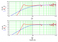
Here is the best modelisation I obtain for a BLH.
Do you think it's possible to damp out all these spikes by putting absorbing materials in the horn itself ?
I'm not obcessed by 40Hz, but I noticed that almost every music I listen to goes down to 40Hz, and some even go down to 30Hz.
If I want to bring this speaker down to 40hz, it is because I cannot have a subwoofer (too expensive, and I don't have a good place for it anyway).
Dynamics are not really important because I never bring my speaker to its +-2 mm Xmax, except when I wanna listen to music out of my bedroom 😀. Anyway, the woofer displacement cannot be worse than on an open baffle.
I'm almost sure now that BR and DBR cannot bring this speaker down to 40Hz without linearity issues, and TLs don't look so promising unless they are severily stuffed and really large.
Well, if I'm condamned to have a big box, I think I will look for a Back loaded horn enclosure that allows an almost infinite bass extension and an amplified peak response which, if I understand, can be equal to a bigger driver's in a conventional enclosure.
Apart from Martin's BLH sections sheet, is there another tool for simulating this enclosure, cos' I didn't find any on the net ?
Here is the best modelisation I obtain for a BLH.
Do you think it's possible to damp out all these spikes by putting absorbing materials in the horn itself ?
Attachments
youyoung21147 said:I'm not obcessed by 40Hz, but I noticed that almost every music I listen to goes down to 40Hz, and some even go down to 30Hz.
You should have picked another driver.
-2db at 50Hz is not too bad, is it?
That's simulated, in-room response will probably extend a little more, as long as it isn't a big room and you take care to position them.
Allez.
yes it would be perfect with a sub. Anyway it is the solution I will be condamned to if my back loaded horn project fails.
Room resonnances might help, and I know that my current TQWT's only go down to 70Hz but one of them is in a corner and extends down to 45Hz, with an equalizer.
Thaks for your nice simulations !
I choosed this driver because at this time I didn't know much about speakers and a friend who heard it told me it was outstanding for its size, which is right because I didn't hear anything better concerning sound quality, though bass cannot extend really low.
What I'd like to know right now is if my BLH simulation is accurate enough to start building a new prototype, because cutting wood is expensive and boring
😀 😕
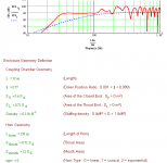
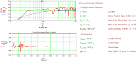
Your coupling chamber is 32 inches long!
Looking at your geometry, I believe you have designed a TL and not a back loaded horn. I have serious doubts that this design will work and it is probably not worth building. Don't believe everything you simulate, you need to ask yourself if the model geometry and calculated results make any sense and if they fit the assumptions that went into deriving the equations.
Looking at your geometry, I believe you have designed a TL and not a back loaded horn. I have serious doubts that this design will work and it is probably not worth building. Don't believe everything you simulate, you need to ask yourself if the model geometry and calculated results make any sense and if they fit the assumptions that went into deriving the equations.
Yes, I know the geometry is quite amazing and doesn't look like a standard BLH. That was just a simulation example and I wouldn't have built this thing anyway, due to its size.
Some little questions about the sheet :
Is it as accurate as your ML-TLs sheets, which work perfectly well, because you seem not to have really tried it according to your website ?
Is it interesting to consider the "sound pressure in time domain" graphic to adjust the geometry, because a horn seems to send back the impulsion through the mouth with a delay, but amplified too. Does it mean a horn always has some coloration, and is it possible to increase the impulse impact of the driver with a horn ?
Is it possible to model some damping in the horn, like in the coupling chamber ?
Yes, I know the geometry is quite amazing and doesn't look like a standard BLH. That was just a simulation example and I wouldn't have built this thing anyway, due to its size.
Why present something for comment if you have no intention of building it? If you are going to post nonsense designs, looking for feedback, then I am not sure how long you will continue to get useful comments.
Is it as accurate as your ML-TLs sheets, which work perfectly well, because you seem not to have really tried it according to your website ?
The BLH worksheets on my site use the same assumptions as the TL worksheets and produce the same type of calculated response. The BLH and ML TL accuracies are the same. However, for a BLH to be of reasonable size it needs to interact with the walls and floor so that the mouth size can be reduced. This capability is not included in the current worksheet and requires the user to recognize and adjust the design for this effect. My newer BLH models take this into account. To date I have not found a BLH design that I considered good enough to actually build and then correlate against the newer MathCad worksheets, I am still working on this project.
Is it interesting to consider the "sound pressure in time domain" graphic to adjust the geometry, because a horn seems to send back the impulsion through the mouth with a delay, but amplified too.
I believe that a double pulse is an inherent property of a BLH. A TL does the same thing but to a lesser extent due to the fiber damping in the line. The key question, is it audible and does it degrade the BLH performance? I have heard strong opinions expressed both ways on this issue, my guess is that this is not a big problem. Secondary pulses will also be generated at room boundary conditions and if managed they are not huge issues.
Does it mean a horn always has some coloration, and is it possible to increase the impulse impact of the driver with a horn?
The BLH horn's pulse will always be stronger then the driver's pulse, that is the whole point of horn loading. The only way I see of increasing the driver's pulse is to add a front loaded horn, I am still working on that simulation. The horn's pulse will always lag the direct pulse from the driver due to the extra distance is has to travel along the length of the horn.
Is it possible to model some damping in the horn, like in the coupling chamber?
Yes, all of the models will accept up to 1 lb/ft^3 of fiber damping at any section. You will have to hand edit the input if you want a custom and optimized distribution of fiber damping.
You have a very good driver with the F120A, if you use it correctly I think that you could have a very good finished speaker system. My advice is to design and build a ML TL style of enclosure tuned to the driver's fs (using measured T/S parameters) and not chase something that stretches the driver's intended application too far based on incomplete input information. Adding an appropriate BSC filter, to get a balanced SPL response, and you should have a very high performance speaker system. Don't look for room shaking deep extended bass from a small driver, it cannot move enough air to replace a 10 inch or bigger sub.
Generally speaking, I've always found it a bit of a mistake to try and push a full range driver in a TQWT down too far. My preference with the FX120 would be a design that gets to 75 hz or so, with no peaking at Fc, and about 3 db of excessive gain 100-300 or so. Others prefer to design for dead flat FR and use a choke/resistor for BSC. Either way 'works'.
GB
GB
I've played with all the parameters of the BLH worksheet and finally, I obtain something which looks correct and extends the FX120 just like I want, with a decent horn length that can be gently folded so it doesn't take too much place. (the first design geometry I showed was just the best thing I obtained at this time)
Greg D : I really cannot accept an enclosure that only extends down to 75Hz, because then I will miss half of the music. As I have no sub, I prefer more bass at the expense of maybe less dynamics, as I have a small room.
I found it a little astonishing to obtain the same results with a 12 and 19 in long coupling chamber, with the driver placed at different points. The 12in chamber would have been perfect, but due to the driver's size which cannot fit into it, I must use the 19in long chamber.
As the chamber has a small internal volume, how should be considered the interactions caused by the magnet's volume, which is quite big on the FX120 ?
Concerning the tapper, I suppose "linear taper" means it will look like a TL design = parallel sides and a constant cross sectional area expansion, making it look like a little like a triangle seen from the side of the horn isn't it ?
And in the worksheet, I do not understand how to enter the sections by hand, as there is no space visually defined for the 10 sections, like in the TL sections sheet (I'm not really a crack at maths, unfortunately )
)
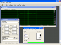
Here are some screen captures of the best modeling I obtain. I took care of the impulse response to balance the whole work, and it seems like I will increase the impact of the driver with this geometry, a nice thing for a fullrange system😀
I prefer not to reduce the mouth size because the speakers might not be placed on the floor of my room, but maybe (maybe) on my desk (I know, it looks strange )
)
Greg D : I really cannot accept an enclosure that only extends down to 75Hz, because then I will miss half of the music. As I have no sub, I prefer more bass at the expense of maybe less dynamics, as I have a small room.
I found it a little astonishing to obtain the same results with a 12 and 19 in long coupling chamber, with the driver placed at different points. The 12in chamber would have been perfect, but due to the driver's size which cannot fit into it, I must use the 19in long chamber.
As the chamber has a small internal volume, how should be considered the interactions caused by the magnet's volume, which is quite big on the FX120 ?
Concerning the tapper, I suppose "linear taper" means it will look like a TL design = parallel sides and a constant cross sectional area expansion, making it look like a little like a triangle seen from the side of the horn isn't it ?
And in the worksheet, I do not understand how to enter the sections by hand, as there is no space visually defined for the 10 sections, like in the TL sections sheet (I'm not really a crack at maths, unfortunately
)Here are some screen captures of the best modeling I obtain. I took care of the impulse response to balance the whole work, and it seems like I will increase the impact of the driver with this geometry, a nice thing for a fullrange system😀
I prefer not to reduce the mouth size because the speakers might not be placed on the floor of my room, but maybe (maybe) on my desk (I know, it looks strange
)Attachments
- Status
- Not open for further replies.
- Home
- Loudspeakers
- Full Range
- Fostex FX120 : the second part...