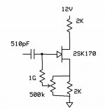
Thanks to someone on another board for this trick. Though I'm not sure he was certain of the mechanism. The simple source follower/phase splitter has a deep null of seconds (the dominant normally) at a "magic" bias point. Really quite remarable since the cancellation flips phase it can be an infinitely deep null. The point I got was around 1.5mA of bias (circuit shown).
Yes the null is like an impedance bridge so it is sensitive to everything, you can even tune it with supply voltage. The modulation of Cgd works with the input capacitance to make a voltage cancelling the Vgs seconds. Remember sin(f)**2 makes cos(2F) so the phase is just right.
I know G-Ohm resistors aren't for everyone (could probably get away with a little less here). I wonder if this explains any listening impressions, probably not except for microphones.
Attachments
Can you show some graph (simulated or real)
where we can see the benefit of this.
I am sorry I can not see the actual benefit we get. And how big is this benefit.
But probably it will lower distortion in some respect.
The usual before & after, with & without 😉
would give us a hint how good this works.
Regards
where we can see the benefit of this.
I am sorry I can not see the actual benefit we get. And how big is this benefit.
But probably it will lower distortion in some respect.
The usual before & after, with & without 😉
would give us a hint how good this works.
Regards
scott wurcer said:Yes the null is like an impedance bridge so it is sensitive to everything, you can even tune it with supply voltage.
That's how I usually do it.
😎
lineup said:Can you show some graph (simulated or real)
where we can see the benefit of this.
I am sorry I can not see the actual benefit we get. And how big is this benefit.
But probably it will lower distortion in some respect.
The usual before & after, with & without 😉
would give us a hint how good this works.
Regards
Sure, there's more to it than I had thought and when I started taking more data my USB A/D & D/A blew up, literally. A loud snap but I could not find the magic smoke, probably an SMT chip delaminated "potato chipping" we call it. Maybe I will look in the lab with some real equipment.
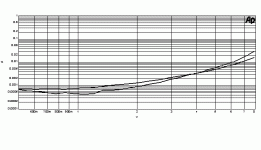
Here's a curve I took once which serves as an example, a 2SK370
operating as a follower biased by a CCS driving 10K at 1 KHz. The
higher distortion curve (1 V output) is with +15V/-15V supply, and
the lower is +13V/-15V, which is about .0004%. When you look at it,
the 2nd is gone, and 3rd plus a little noise and some scattered higher
harmonics are what remain.
The potential differences become more dramatic as the load impedance
goes down. This works on self-biased complementary followers as
well.
😎
Attachments
This example was a follower, but you can see the same phenomenon in
Common source applications. The 2nd harmonic dues to variation in Ids
is cancelled by the variation in Vds.
Common source applications. The 2nd harmonic dues to variation in Ids
is cancelled by the variation in Vds.
Nelson Pass said:This example was a follower, but you can see the same phenomenon in
Common source applications. The 2nd harmonic dues to variation in Ids
is cancelled by the variation in Vds.
Yes, these short channel FET's have terrible modling of output characteristics in SPICE. Yes JC this does not simulate, you have to build it and/or listen to it.
In the microphone application I was fooled by the fact that the voltage coefficient of the Cgd, which is modeled, will show this effect in simulation. In reality this just moves the point of null.
I first saw this effect demonstrated by Bascom King, formerly an 'Audio Magazine' reviewer back in 1972 or so. We made a microphone input stage using this 2'nd harmonic null cancellation technique in Switzerland for a studio board, in 1975, that probably is still in operation. It is amazing that it works, but it certainly does. It is just such a hassle to get and keep the null. I just used it as a common source input, but I will have to study the follower examples more closely.
The ZV9 aka F3 uses this by trimming the cascode voltage for an
LU1014 power Jfet. With a single stage you can get it to do .003%
at 1 watt, and the null holds pretty well without thermal compensation.
And yes, the sim examples I've seen don't seem to do a good job of
predicting the distortion I see with real Jfets.
😎
LU1014 power Jfet. With a single stage you can get it to do .003%
at 1 watt, and the null holds pretty well without thermal compensation.
And yes, the sim examples I've seen don't seem to do a good job of
predicting the distortion I see with real Jfets.
😎
There was an AES preprint from a LA convention in the late 60's by an engineer from a middle European country, who did this sort of cancellation with bipolar transistors. It might be useful to find this paper, for the mathematics, if nothing else.
- Status
- Not open for further replies.
- Home
- Amplifiers
- Solid State
- Fortuitous distortion null in simple FET circuit

