Hello Friends..... 🙂
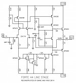
Recently I was contacted by a Forte 44 owner who was looking for a copy
of the schematic. I didn't have it, having left Threshold prior to that product,
but he sent me a picture of the circuit board and it did look similar to the
last front end that I designed for Threshold power amplifiers. He did some
additional work connecting the dots and I managed to fill in some of it, so
here we are.
In this drawing, you will note that dots are made for all crossed connections,
transistors with shorted Collector-Base are used as diodes for current mirrors,
transistors shorted Emitter-Base are used as zener diodes.
The MPSA18 are high gain/low noise, as are the 2N4250. The others are
generic parts, and you all know our mostly unavailable friend the 2SK170 -
you might want to consider the LSK170 replacement.
And thanks to Mr. Baine for his efforts.
😎
Attachments
before anyone else chime in with same question - resistor marked as 200+ , ditto on positive rail - means trimpot ?
tnx , as always
(all that spoon feeding can really choke some of us )
)
tnx , as always
(all that spoon feeding can really choke some of us
)Thank you so much for sharing this one. I am struggling to get mine sorted. DC present on output 🙁
> struggling to get mine sorted. DC present on output
Not much clue.
Did it ever work right since you got it?
A little or a lot of DC? (Numbers are good.)
What about DC around the input stage (which tells the output stage what to do)? If you mark-up the plan with voltage numbers, it may be clear what is broken.
Always check supply voltages first! It rarely makes DC on output, but I hate to chase fine detailed theories when it turns out the rails are so far sick that a finger-test would tell you (but use a meter, it's safer).