Great answer, thanks.
Did you get the autobias circuit strictly because you were using toroid transformers?
Did you get the autobias circuit strictly because you were using toroid transformers?
there would be some trickle current going through it to give the source follower some minimum load. I didn't know if bad things would happen if current stopped flowing through the MOSFET. They may not be necessary.
I have found that some mosfets will exhibit a nasty habit of emitting a short burst of high frequency energy (3 or 4 cycles) just as they return to conduction, so the resistors may indeed be necessary.
I have seen this in screen drive and conventional G1 drive amps. It doesn't occur in all cases, but follows the mosfet when I swap parts on identical driver boards.
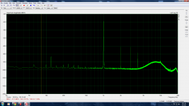
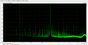
I just took distortion measurements. They are not as low as I had hoped, but I think that if I were to play with the pot in the anode loads of the first stage, I might be able to null out some of the 2nd harmonic. I think the 841s are my dominant source of distortion here and noise as well. Notice the weird noise hump in the 5-10k frequency band that they exhibit.
Honestly, it sounds pretty good right now. The Plitron transformers have unbelievable bass and treble. The speakers I have connected to it are pretty efficient so I don't think the amp is working too hard, so it probably is not producing too much distortion at my listening volumes.
Visible clipping occurs at about 25V peak into 8 Ohms, so somewhere around 40Wrms.
The amp I built for my brother in this thread had much better distortion performance, although I think this Unity Coupled amp probably has lower Zout.
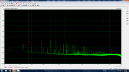
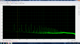
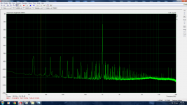
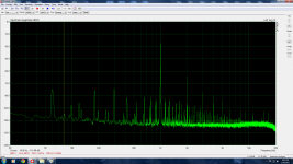
I attached distortion measurements at 1W and 10W. I have a baseline with the amp powered off and one with it powered on. I also have the 841s at 230Vrms output showing the weird noise hump and their ability to swing large voltages at relatively low distortion.
A note about my test setup: I use a version of Pete Millett's soundcard interface that I built with a high impedance input so I could use a 100X probe to take measurements of stages that were very sensitive to loads and swung very large voltages(like my 841 stage). I think this and the fact that I am just using a super crappy soundcard to do the measurements are the sources of all of my extra noise that gets picked up.
Honestly, it sounds pretty good right now. The Plitron transformers have unbelievable bass and treble. The speakers I have connected to it are pretty efficient so I don't think the amp is working too hard, so it probably is not producing too much distortion at my listening volumes.
Visible clipping occurs at about 25V peak into 8 Ohms, so somewhere around 40Wrms.
The amp I built for my brother in this thread had much better distortion performance, although I think this Unity Coupled amp probably has lower Zout.
I attached distortion measurements at 1W and 10W. I have a baseline with the amp powered off and one with it powered on. I also have the 841s at 230Vrms output showing the weird noise hump and their ability to swing large voltages at relatively low distortion.
A note about my test setup: I use a version of Pete Millett's soundcard interface that I built with a high impedance input so I could use a 100X probe to take measurements of stages that were very sensitive to loads and swung very large voltages(like my 841 stage). I think this and the fact that I am just using a super crappy soundcard to do the measurements are the sources of all of my extra noise that gets picked up.
Attachments
I have found that some mosfets will exhibit a nasty habit of emitting a short burst of high frequency energy (3 or 4 cycles) just as they return to conduction, so the resistors may indeed be necessary.
I have seen this in screen drive and conventional G1 drive amps. It doesn't occur in all cases, but follows the mosfet when I swap parts on identical driver boards.
Yeah, I don't see any real reason to take them out although they freaked me out a bit when I fired up the output stage for the first time. I thought, "Oh no, I can't shut the output tubes completely off even with -85V on the grids!" Then I remembered the little bit of current that bypasses the tubes there.
So when I initially got this amp together, I flipped it right-side-up a bit prematurely. I realized later that I had not adjusted the pots in the input stage plate loads to null out the gain imbalance in the driver tubes. The problem was that the amp was so heavy that every time I thought about flipping it over to make the adjustments, I just felt this overwhelming lazy feeling and flipped on the music instead. Besides, it sounded quite good despite making almost 1% distortion at 10W.
Anyway, today I finally got back to it and I'm really excited with the distortion measurements with everything tuned up.
I measured:
0.025% @ 1W
0.15% @ 10W
0.22% @ 20W
0.24% @ 30W
clipping occurs at ~ 40W.
All were 2nd harmonic dominant, despite this being a push-pull amp. I could really get that 2nd really low by introducing imbalance in the phase splitter, but I never could get it under the 3rd.
All in all, I think these are pretty good figures for an open-loop amp.
Tomorrow I will be making frequency response measurements. I would like to see how close this amp comes to making the 500kHz that van der Veen claims that these transformers are capable of.
So I tested bandwidth. The amp was down 3dB at 120kHz. I'm guessing that the limiting factor in the amp is the 841 driver stage. I did some back-of-the-envelope calculations and it looks like since the 841 has such a high plate resistance, it only takes a 22pF load to put it 3dB down at 120kHz. An 801A would probably perform much better here in terms of bandwidth but they are too expensive and I don't really need to make an amp with half a megahertz of bandwidth.
I knew that would be the price of using a high-impedance triode as the driver, but the 841's curves sure are pretty. The other thing about the 841s is that I think they are the dominant noise source in the amplifier. I think those white-hot filaments combined with the high plate resistance aren't particularly good for low-noise design. This amp has a tiny bit of background hiss (with ear close to the tweeter), whereas other amps I have built have had none, and I used the same input stage I always use.
That said, I spent a bit of time listening after making the adjustments, which mostly just took out a bunch of 2nd harmonic distortion, and I think that modern pop or heavily electronic music definitely sounds better now, but simpler songs sound slightly less alive. I would say that songs with lots of electronic sounds and loud bass lines are now subjectively clearer.
My conclusion: The 2nd harmonic distortion can add a pleasant effect to sounds, but any non-linear transfer function, even if it only generates even harmonics, will generate IM products all over the place when you start mixing a lot of sounds together. Those IM products don't sound good and will muddy the sounds if you start mixing enough together.
I tried measuring the -3dB point on the low end. I got down to 10 Hz and was still at full amplitude. I started thinking, "Am I doing something wrong here?" I have a setup that can get to 5 Hz that I will try later. Of course, these bandwidth measurements are small signal measurements.
The bandwidth would be smaller at full power. The data sheet for the output transformer claims full power bandwidth(-3 dB @ 70W) from 14 Hz to 450 kHz.
The bandwidth would be smaller at full power. The data sheet for the output transformer claims full power bandwidth(-3 dB @ 70W) from 14 Hz to 450 kHz.
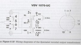
I found, on page 111 of Menno Van der Veen's book "Modern high end valve amplifiers based on toroidal output transformers" mentioning the impedance of the extra secondary winding as 5 ohm. This is the first and only place I've seen this reference as shown in the photo below.
Do you suppose this secondary is basically the same as the speaker secondary? And if so what about connecting two in series for "10 ohm" output? That would allow a nominal 3200 ohm primary for an 8 ohm load.
Do you suppose this secondary is basically the same as the speaker secondary? And if so what about connecting two in series for "10 ohm" output? That would allow a nominal 3200 ohm primary for an 8 ohm load.
Attachments
I just sent you a PM, but I think it is probably a smaller wire on the feedback winding, at least that's what I always assumed. I would try emailing Plitron to ask, though. If they don't respond, I can take a resistance measurement of the two secondaries on the transformer but that would involve carrying the very heavy amp to the garage so let's try email first 🙂.
I'd be very interested if they are equal windings that could be run in parallel for a substantial reduction in Zout. The Zout of this amp is just over 1 Ohm with no feedback around the transformer. If I could halve the secondary resistance, Zout would drop almost a tenth of an Ohm, which would be nice. I just always assumed it was a thin wire and I don't think I ever tried to measure it. Maybe I did. I'll check my lab notebook.
I'd be very interested if they are equal windings that could be run in parallel for a substantial reduction in Zout. The Zout of this amp is just over 1 Ohm with no feedback around the transformer. If I could halve the secondary resistance, Zout would drop almost a tenth of an Ohm, which would be nice. I just always assumed it was a thin wire and I don't think I ever tried to measure it. Maybe I did. I'll check my lab notebook.
I'll email Amplimo as I cannot find Plitron offering any of the output transformers anymore on their website.
Did you know that Trafco Torusni transformatori - Uvod also supplies these? Amplimo and Trafco are the only two suppliers of any of the Van der Veen transformers as far as I can find.
Did you know that Trafco Torusni transformatori - Uvod also supplies these? Amplimo and Trafco are the only two suppliers of any of the Van der Veen transformers as far as I can find.
Two '5 ohm' windings in series make a '20 ohm' winding.
Indeed that is correct. Yet another senior moment on my part for those keeping score.
Well, it is certainly good news for people who want to build a Unity-Coupled amp that there is another transformer supplier with pretty reasonable prices.
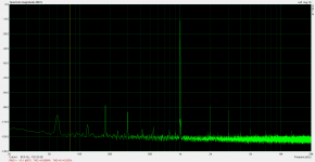
If I were doing this amp again I would do it a bit differently. I used a rare and exotic tube as the driver because I wanted the challenge of A2 and I wanted a thoriated tungsten filament, however I have since tested a driver that is much better suited to the task. I have attached amplifier distortion at 30W, 841 driver distortion at about that same level (100Vrms), and distortion of the new circuit at the same level as the 841 driver (a CCS-loaded EL34 with shunt feedback).
I think it would make a big improvement to the amp, but I am so hesitant to pull those 841s out of there. They're purdy.
Attachments

I started a thread on a Unity Coupled amp using the Vanderveen transformers here:
Unity Coupled Amp Using Vanderveen VDV-1070-UC Output Transformers | Audiokarma Home Audio Stereo Discussion Forums
Unity Coupled Amp Using Vanderveen VDV-1070-UC Output Transformers | Audiokarma Home Audio Stereo Discussion Forums
- Home
- Amplifiers
- Tubes / Valves
- For Your Consideration: Unity Coupled Plitron Amp, No Bootstrapped Driver, No GNF