I've read that because carbon comps have zero inductance that makes them better as grid stoppers. Now I'm confused...
Maybe I'll split the difference and use metal film.
Why, exactly? It seems to me all you'd be doing is increasing the noise in the first stage, where you really don't want it.
I have a genuine Aikido Phono PCB in the closet, waiting for me. That thing's gigantic, like 12cm x 30cm for just the audio circuits. That PCB alone would take up the entire chassis this current phono preamp is in, connectors, audio circuits and power supply all in. There comes a point, ya know...
Oxide shouldn't be inductive at all... MF might be but it's a film, not a coil.
Degenerative action of the cathode resistor? I dunno.
Ya mine will fit in a 12" depth chassis. I didn't do the Aikido'ing because I think a clean PSU is a better idea.
Last edited:
kodabmx said:I'd be interested in if Merlin ever tested 6N2 like the 12AX7...
I'm a big fan of Merlin's Designing High-Fidelity Tube Preamps book. Merlin did test some 6N2P for noise, and found them to be very good. The other nice thing about them is that their input capacitance is appreciably lower than a 12AX7's, which makes them better for use with contemporary MM carts like Audio Technica, which are rated for 250pF max load capacitance. A bypassed-cathode 12AX7 with strays probably has Cin of 200pF. Add another 100pF to 150pF for the tonearm cable and you've exceeded that maximum by a good long way. I'll comment on that after I get the noise down a bit.
You can also bypass an LED. Only that its bypass capacitor must be 1000uF or bigger to be effective down to low frequencies because the LED has low impedance. They are not huge such caps when of low voltage rating. Its only an LED's VF drop they have to withstand in a cathode circuit. 1000uF has 8Ω impedance at 20Hz and only 1.6Ω at 100Hz so if the LED has 20Ω the signal will prefer the capacitor's route in its most significant portion.
MerlinB in the phono preamp example in his afore-mentioned book bypasses the red LED in the first stage cathode with 220uF. I have some fancy organic polymer 1000uF 16V which I could use. Do you really think that could make a big difference? If you do, I'll add it to my list of things to do when I start swapping parts in the audio boards again.
However, I don't want to take the preamp completely apart until I have a finite list of things to try. I already have to replace the input wiring with shielded coax, which I will probably do tonight and reassemble so I can hear the difference. But I don't want to ruin the audio PCBs by desoldering parts too many times.
kodabmx said:I didn't do the Aikido'ing because I think a clean PSU is a better idea.
Broskie's assertion is that Aikido-ing the power supply noise and then adding a quiet B+ gives you really silent backgrounds, so results in a better sounding preamp. That makes sense to me. He does not assert that because of the Aikido mojo you don't have to regulate or thoroughly filter the B+ supply for a low-level preamp.
--
Last edited:
Bypassing the LED will give back any small gain loss its impedance robs through the local negative feedback it creates at the cathode and it will also shunt to ground the LED's own little noise. That's the technical account. Subjectively I think its discernible in making the sound bit smoother but your mileage may vary.
Thanks Salas, but my question is about the value of capacitance to use bypassing the LED.
I have the red LED bypassed with 220uF.
Will increasing that bypass cap to 1000uF make a substantial improvement? Or only a technical improvement that is not discernible by ear?
I have the red LED bypassed with 220uF.
Will increasing that bypass cap to 1000uF make a substantial improvement? Or only a technical improvement that is not discernible by ear?
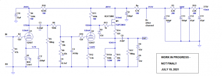
Here is the schematic of the preamp in its current state (attached image).
I'm contemplating changing...
1) C2 from 220uF to 1000uF
2) R2 from 120R to larger value? Or don't change it?
3) R10 from 120R to 1k
4) twisted pair wiring to input; replace with shielded coax
5) add ferrite beads to input wiring
6) add push-on tube shields (if I can find them...)
Anything else I should do?
Thanks again for your inputs!
Attachments
Oh man... I found the source of the hum!
It's the damnable television. Even on standby it injects hum into everything. It's likely forming a ground loop. I'm going to put a switch in line with its AC cord so I can power it off completely for listening sessions.
The Raspberry Pi is exonerated. Turning it off/on makes no difference in the noise heard from the speakers when the phono preamp is selected and the volume is set to maximum.
The noise from the preamp is actually not bad at all. It's character is very much a soft, low 60Hz -- not the buzzier sound from before. Yup... RFI.
Phew!
However, you all have made some excellent suggestions for improvements, which I'm going to try to implement. In today's ridiculously RF-riddled world, a high impedance phono preamp is vulnerable to noise sources. It can't hurt to minimize those problems as much as possible, right?
Last edited:
Thanks Salas, but my question is about the value of capacitance to use bypassing the LED.
I have the red LED bypassed with 220uF.
Will increasing that bypass cap to 1000uF make a substantial improvement? Or only a technical improvement that is not discernible by ear?
It will clean up the lower bass further. 220uF has 36Ω at 20Hz when 1000uF has 8Ω. I don't know if you will discern it, depends on speakers size and arm resonances too.
Salas said:I don't know if you will discern it, depends on speakers size and arm resonances too.
Did you say arm resonances? Having experienced what subsonic resonances can do to the reproduction quality when I had too small a value of decoupling resistor going to the first stage, anything I can do to keep from exciting a subsonic resonance is alright with me. The 1000uF bypass caps (C2) are officially on the to-do list.
Thanks for the advice Salas. I appreciate it.
Oxide shouldn't be inductive at all... MF might be but it's a film, not a coil.
I remembered M. Jones and M. Blencowe both mentioning that metal film and carbon films have a helical track cut in the resistive layer to define the resistance of the device. A helix is basically a winding, so this construction makes at least a little tiny bit of inductance.
Metal film:
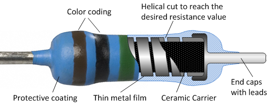
(Metal oxide film are very similar, but have tin oxide in the metal film to add some resistance.)
Carbon film:
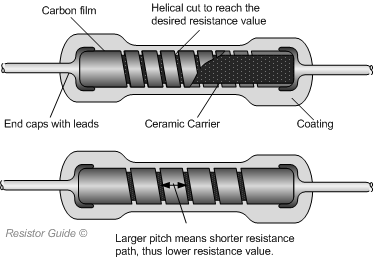
Carbon composition resistors are basically a little box filled with carbon powder interspersed with non-conductive particles to create the desired resistance value. No helical cut 'coil' shape, so only trace inductance.

Just FYI, thought you might be interested.
--
If that's true, then all resistors are basically the same. For all intent and purposes RE: tube circuitry .
According to M. Jones and M. Blencowe...
Not for noise, resistance value stability, or even linearity.
Carbon comp resistors are prone to making noise (e.g., crackles and pops when used as plate loads) and also drift a lot in value, especially if heated and reheated on a regular basis over time.
Carbon comp resistors distort(!) high signal levels going through them. (They add measurable levels of harmonic distortion.)
Carbon film resistors also add a smaller, but measurable bit of harmonic distortion.
Metal film and wirewound resistors generally do not add enough harmonic distortion to be discernible.
Small value wirewound resistors are inductive enough to possibly interact with tube inter-electrode capacitances, etc. (That's why there are non-inductive wound wirewound resistors.) According to M. Jones, wirewound resistors of 10k or higher resistance have so little inductance that it's not worth worrying about, so go ahead and use regular inductive-wound ones as tube plate loads (10k, 12k, 15k, 18k, 22k, 27k, 30k, 33k, 39k, 47k are the usual suspects).
Carbon composition resistors have far worse random fluctuations of their resistance than any of the other types. That causes 1/f noise when there is a DC current flowing through them. When there is a signal current flowing through them, they produce noise sidebands around the signal.
In the case of a grid stopper, there is hardly any current flowing through the resistor. A resistor that doesn't carry any current just produces thermal noise with a level that depends on its value and nothing else. That is, a carbon composition resistor used as a grid stopper doesn't get the chance to produce excess noise. 1 kohm will give you about 4 nV/sqrt(Hz) and 100 ohm about 1.3 nV/sqrt(Hz) no matter what type of resistor you use.
One of the last things the late DF96 did on this forum was trying to explain that a small inductance doesn't matter for a grid stopper. I didn't understand that at first, but I guess it's because a large enough grid stopper will get rid of any negative resistance and make the circuit stable for any passive source impedance. If he was right, then you can just as well use any other type of resistor as a grid stopper.
If Luxman cl34 is using 3k3(phono input) and 22k + the series resistors made from 100k + 200k potentiometers as grid stoppers for line input , so can you...Removing RF noise today is more useful than trying to have -140db noise on a phono preamp...You already have R6 as a huge value resistor not causing any significant noise.10...22k in series with the second tube's grid won't matter as noise compared to R6 .Here is the schematic of the preamp in its current state (attached image).
I'm contemplating changing...
1) C2 from 220uF to 1000uF
2) R2 from 120R to larger value? Or don't change it?
3) R10 from 120R to 1k
4) twisted pair wiring to input; replace with shielded coax
5) add ferrite beads to input wiring
6) add push-on tube shields (if I can find them...)
Anything else I should do?
Thanks again for your inputs!
C2 is also able to offer you a high pass filter removing subsonic , so bettrer keep it lower in value to get rid of frequencies below 10 hz!
Last edited:
One of the last things the late DF96 did on this forum was trying to explain that a small inductance doesn't matter for a grid stopper. I didn't understand that at first, but I guess it's because a large enough grid stopper will get rid of any negative resistance and make the circuit stable for any passive source impedance. If he was right, then you can just as well use any other type of resistor as a grid stopper.
I think DF69 had some RF knowledge on this too (reading his posts for a different reason). Simply put, given the signal and the purpose I got the impression that people were over concerned with the small inductance of metal film axial etched resistors (ie making a small inductor) vs the benefit of having the resistance in the grid to utilise the miller capacitance as a LPF. The AF valves having enough internal capacitances to really make any resistor inductance irrelevant for the frequency range (actually adding capacitance may help). Getting the stopper as close to the pin as possible (even using a SMD part) is probably more of a concern.
Last edited:
If Luxman cl34 is using 3k3(phono input) and 22k + the series resistors made from 100k + 200k potentiometers as grid stoppers for line input , so can you...Removing RF noise today is more useful than trying to have -140db noise on a phono preamp...
I believe I'm coming around to thinking that.
The combination of 3.3k ohms in series with 200pF (the approximate Miller C of a fully bypassed 12AX7) gives F3 = 240kHz. That's probably high enough not to make any discernible difference in audio response at 20kHz.
Since 1k ohms series with 200pF gives F3 = 800kHz, I suppose that would have zero effect on the audio frequency range, and wouldn't filter out high frequency noise from switching power supplies either.
Once again, it's a compromise between this and that. Perhaps 3.3k is a good choice for R2.
C2 is also able to offer you a high pass filter removing subsonic , so bettrer keep it lower in value to get rid of frequencies below 10 hz!
Well... There is the question of impedance and PSRR. With a small value C across the cathode bias LED, impedance at the cathode would spike up at the extreme low end, leaving PSRR diminished at those subsonic frequencies. While the audio response would be attenuated down there, a power supply or tonearm/cartridge resonance down there could get excited (which I think was Salas' point).
Another case of a compromise between this and that?
Why are you using an LED for bias in the first place?For higher gain and lower noise you get audible distortions...Use a resistor instead! Much better sound!
You can see my comment from 2018 there too, as i had a very recent experience at the time with using LED's for biasing a D3A phono preamp with passive riaa.
This one?
This one?
This one? (which is about unbypassed cathode resistor for bias)
Sorry, I'm not following you. Please clarify. Much appreciated.
EDIT TO ADD:
I prefer unbypassed cathode resistor too. But that's not a good plan for the input stage of a phono preamp where linearity is not the issue, but gain with low noise is. Therefore, the 'contest' is between a cathode resistor fully capacitor bypassed, or an LED (with capacitor bypass to filter residual noise).
LED's will get you better S/N ratio, higher gain and higher distortion figures as the valves biased that way will saturate easily, no resistor-no feedback...I usually go with a combination of resistor//capacitor+resistor or resistor + led to get some feedback.
This one?
Led's are totally favoured in low noise preamps, but they are pretty useless in power amplifiers as you need to controll the distortion figures locally , more than you could do with a global feedback using the higher amplification given by the LED low dynamic resistance .The schamatic run in a symulator could tell us more about the LED +global NFB vs Resistor .+ local NFB
This one? (which is about unbypassed cathode resistor for bias)
You're right PRR! I used all the bias combinations in the past and always found the resistor better than anything else , allthough you have to deal with the lower gain .The resistor is adding some noise, but the distortion reducing mechanism it allows will give lower thd+N when working.
Sorry, I'm not following you. Please clarify. Much appreciated.
EDIT TO ADD:
I prefer unbypassed cathode resistor too. But that's not a good plan for the input stage of a phono preamp where linearity is not the issue, but gain with low noise is. Therefore, the 'contest' is between a cathode resistor fully capacitor bypassed, or an LED (with capacitor bypass to filter residual noise).
Last edited:
There's no contradiction unless taken out of context.You can use LED's if you apply global feedback which you clearly don't in a pasive riaa configuration.That picture is not mine... Difference is that you can clearly hear the distortions in a phono preamp when using led biaing with D3a at a gain of 77.ECC83 has an even higher gain of 100.never tried biasing ecc83 with LED but there should be the same effect.I doubt you need LED bias witha properly deigned passive riaa with ecc83.i built one once and i remember using imple R or RC elf bias.If you're uing RC cathode bypass witha very big capacitor there's a very big chance you get the same respone as a simple LED.When I told you to make the C smaller i didn't see it's paralleleled to an LED.LED's might need just 100nf for bypass to lower the noise , they have a very low dynamic resistance at all audio frequencies anyway so they don't need any electrolitic capacitors around.
- Home
- Amplifiers
- Tubes / Valves
- For RIAA preamp: Large value caps vs. Regulated/Stabilized PSU